1. What I Built
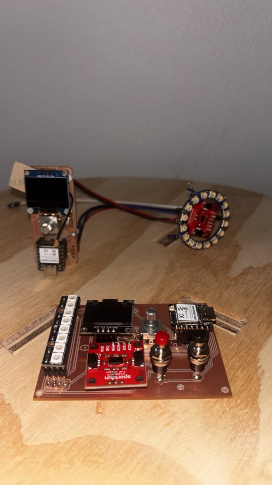
The final project is a wireless MIDI guitar made of two custom boards, each built around a Seeed XIAO ESP32-S3, that talk to each other over ESP-NOW.
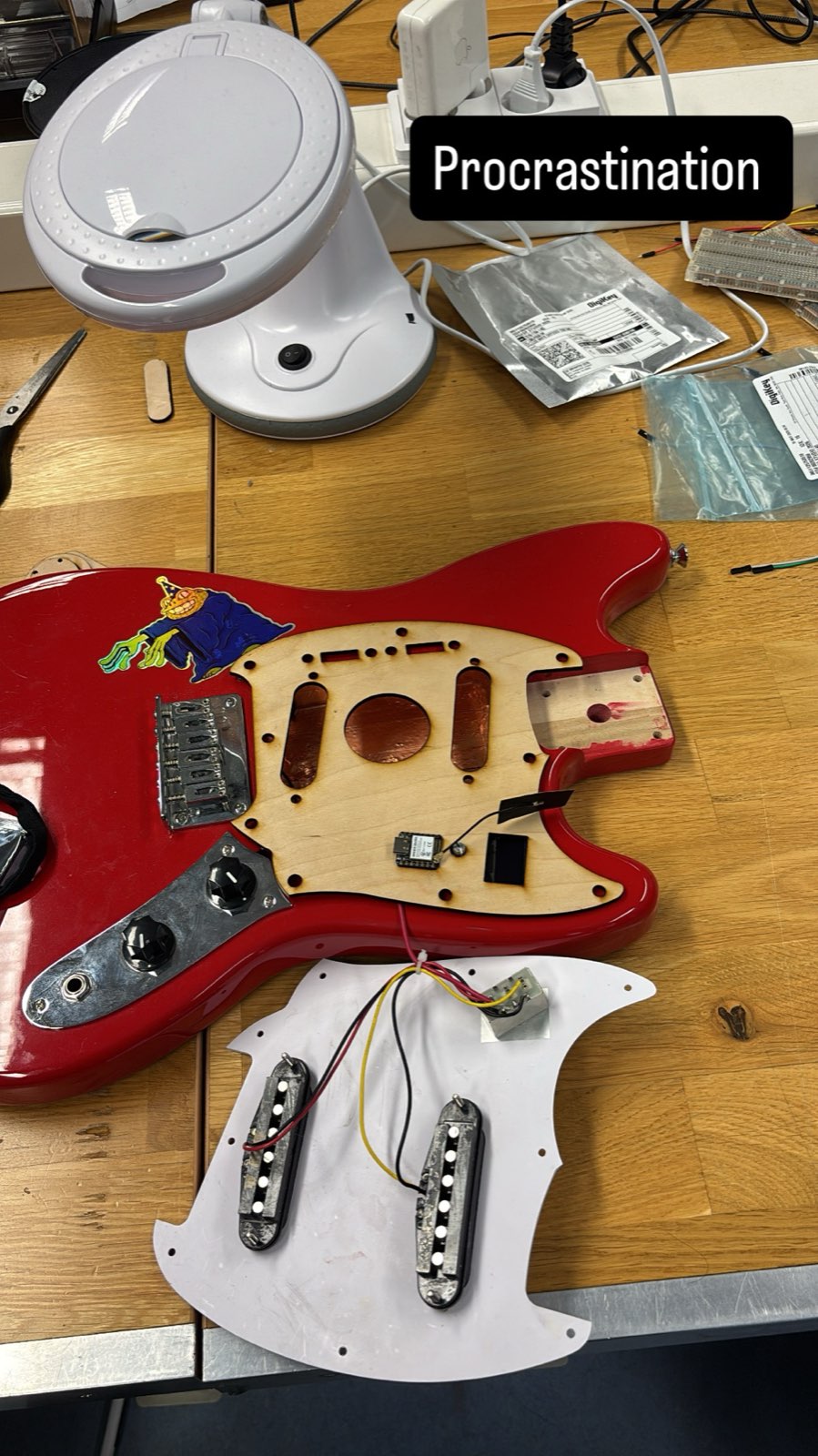
- The transmitter is the controller board from Assignment 09. For this project I routed a pocket into the guitar body so the board sits inside the instrument instead of on the bench.
- The receiver is a new PCB I designed and milled for this project. It listens for the guitar's ESP-NOW messages and forwards them on, as MIDI to a computer, or out to other instruments.
In short: the guitar generates the messages, sends them wirelessly, and the receiver decides where they go.
2. Scope: From Sequencer to Receiver
The original plan was a thermally-controlled sequencer, an extension of an earlier idea. Once I started laying it out I found it was too much to finish well in the time I had, so I narrowed the scope to one clear goal: a dedicated wireless receiver for the MIDI guitar, with the link between them running over ESP-NOW.
Cutting the scope was the right call. It gave me a project I could actually fabricate and test end to end (design a board, mill it, route the guitar to hold the controller, and get the two halves talking) instead of a larger idea left half-finished.
3. The Transmitter: Fitting the Board Inside the Guitar
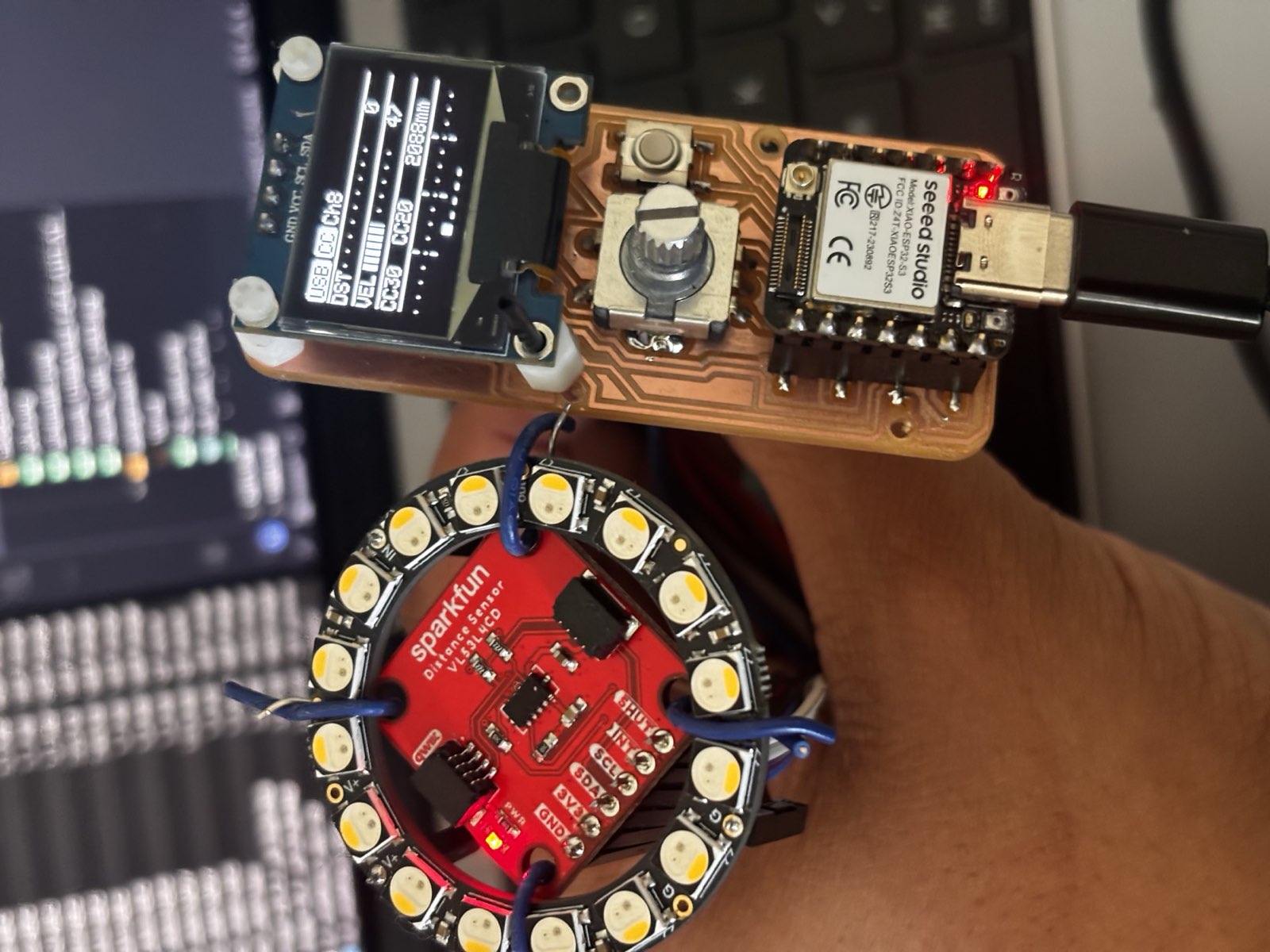
The controller board already worked on the bench from Assignment 09: a XIAO ESP32-S3 reading a time-of-flight sensor, a rotary encoder and a button, driving an OLED and an LED ring. The job here was to get it inside the guitar.
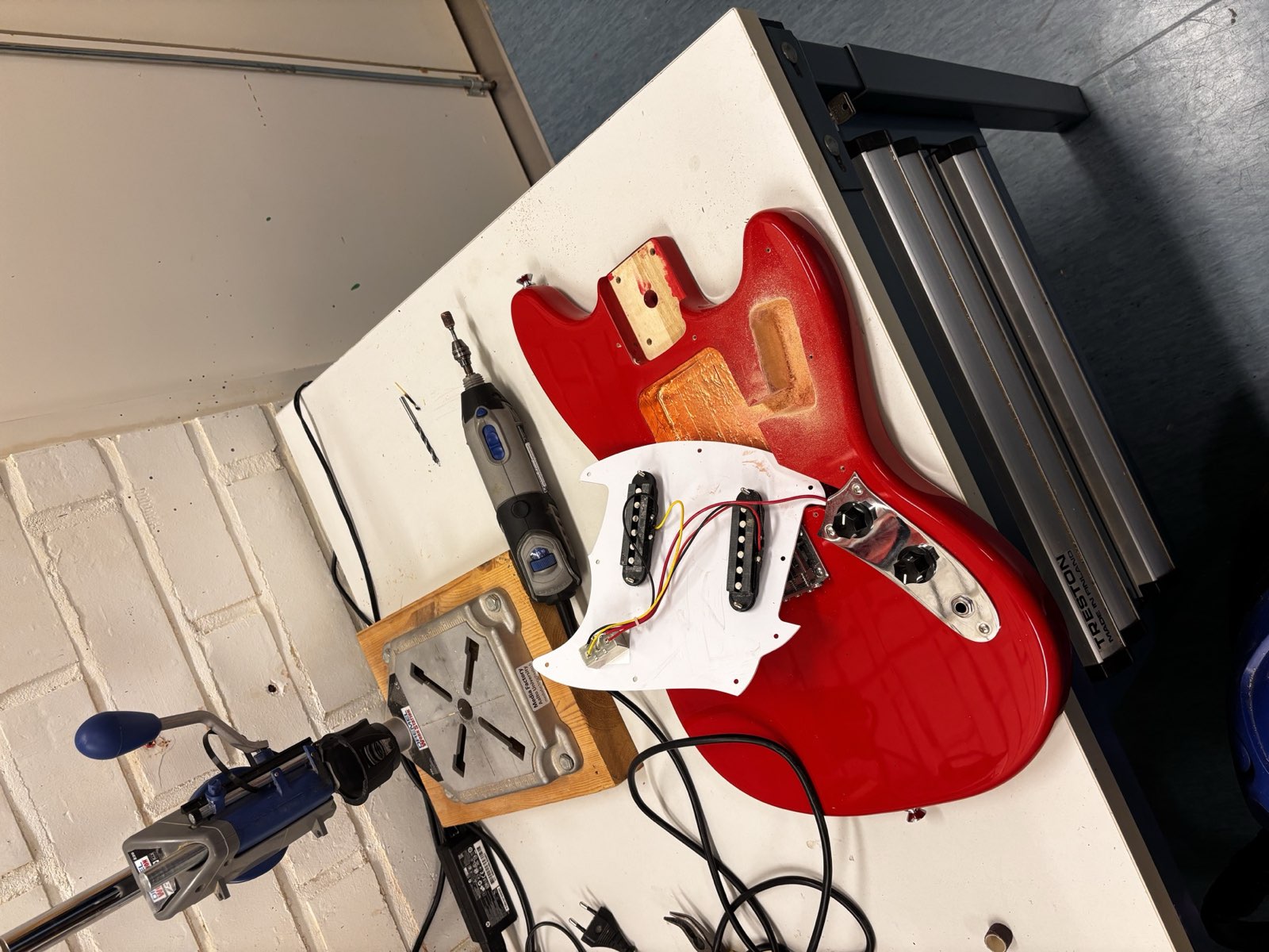
To do that I routed a pocket into the back of the body so the board would sit flush under the pickguard. I cut it at the Fablab with a drill press and a rotary tool, working out from the existing pickup and control routes.
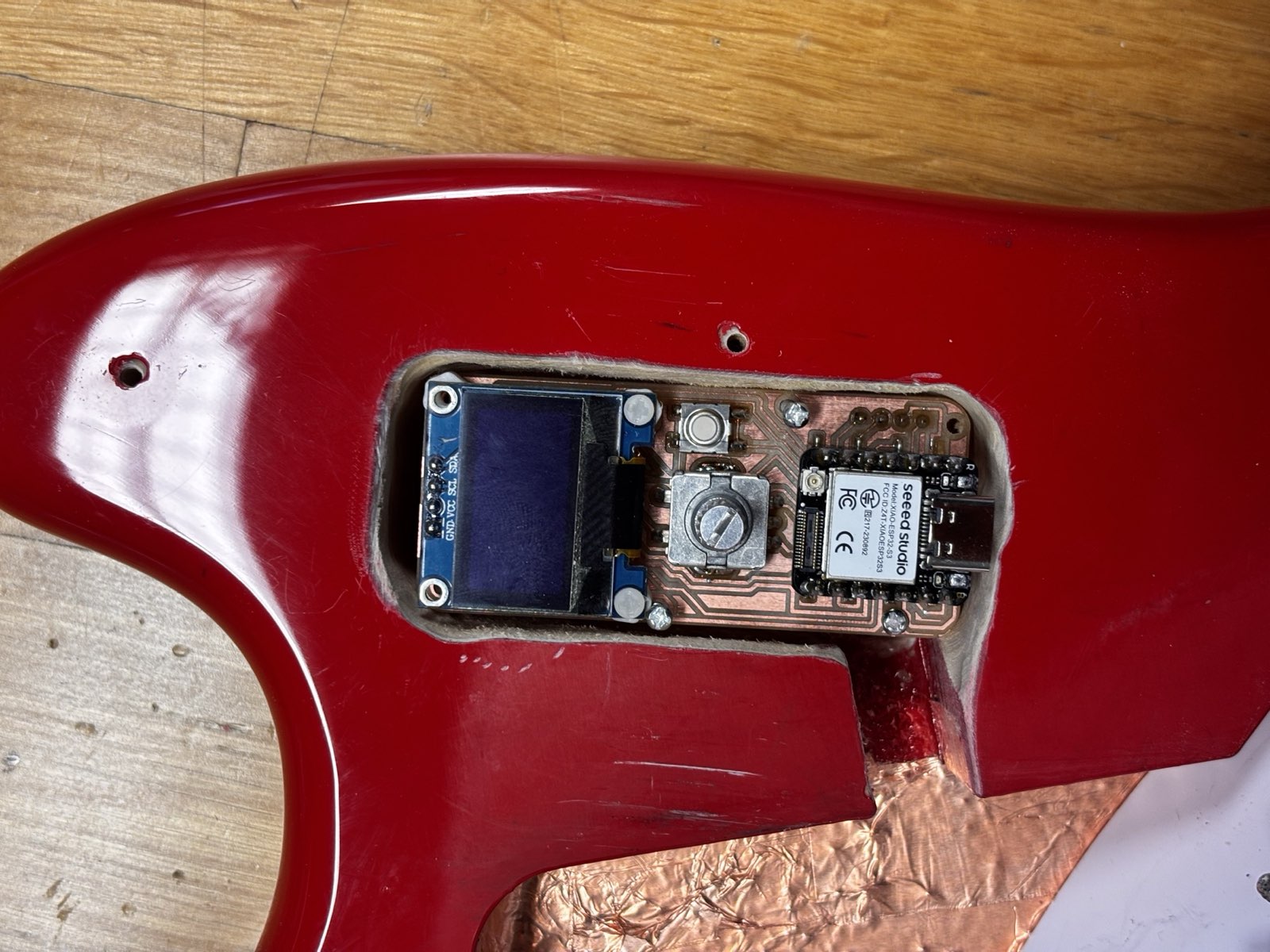
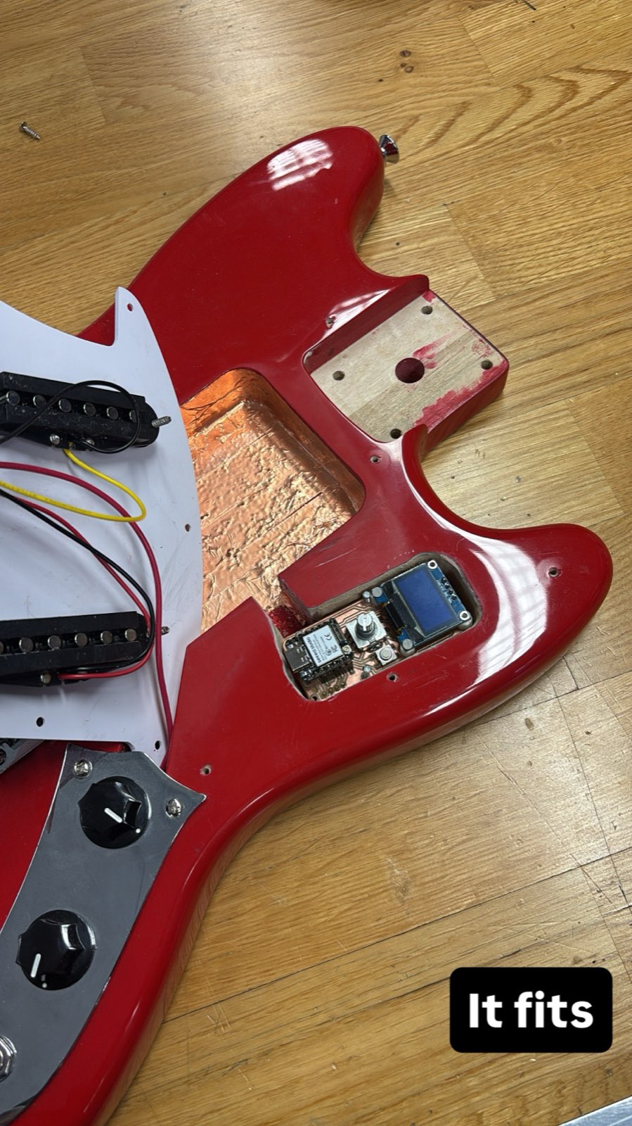
4. The Receiver: A New XIAO ESP32-S3 Board
The receiver is the new piece of hardware for this project. I designed it in KiCad around a second
XIAO ESP32-S3, as a small standalone unit that sits on the desk and receives from the guitar, with a
display, a couple of control buttons and a status LED. My first attempt was a bigger, more ambitious
“pedal” version built around a larger 2.8" Newhaven NHD-2.8-240320AF
TFT and a thermal camera, with a row of 3.5 mm jacks along the top for the outputs.
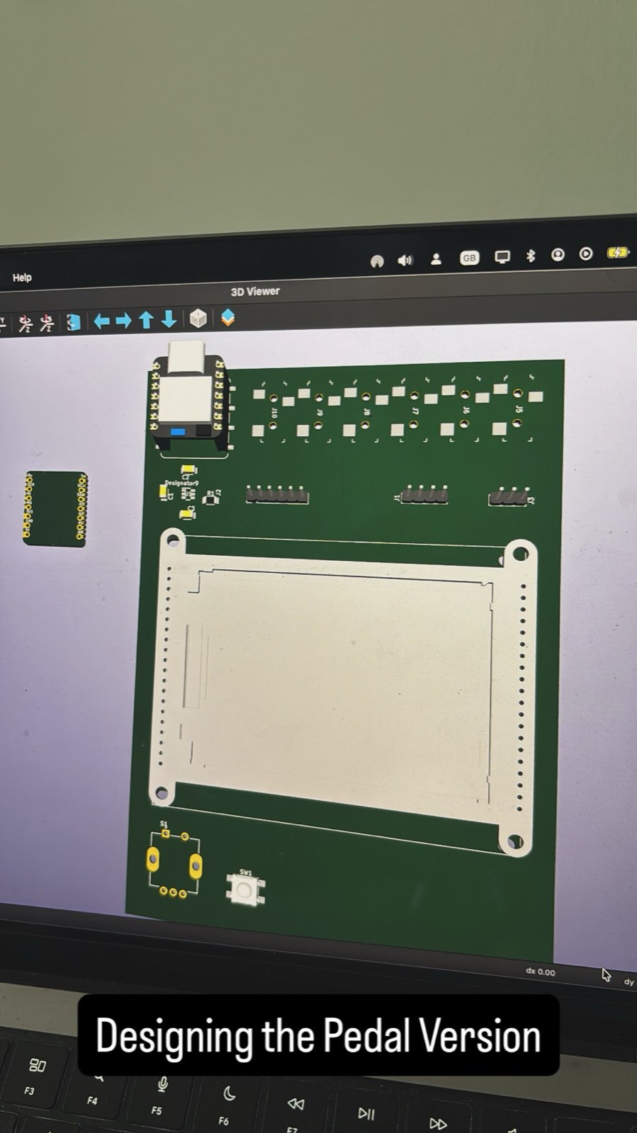
The Newhaven panel doesn't come up in I2C by default, so to drive it over two wires I had to desolder and resolder a configuration pin on the back of the breakout to select the I2C interface.
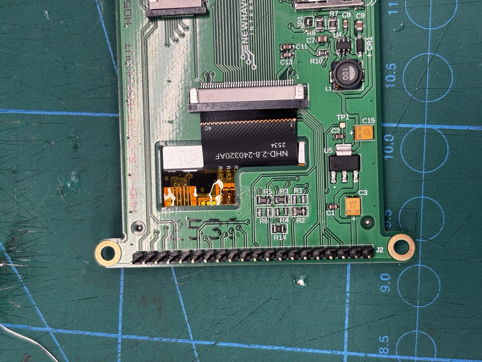
NHD-2.8-240320AF: desoldering and
resoldering the interface-select pin to put the display into I2C mode.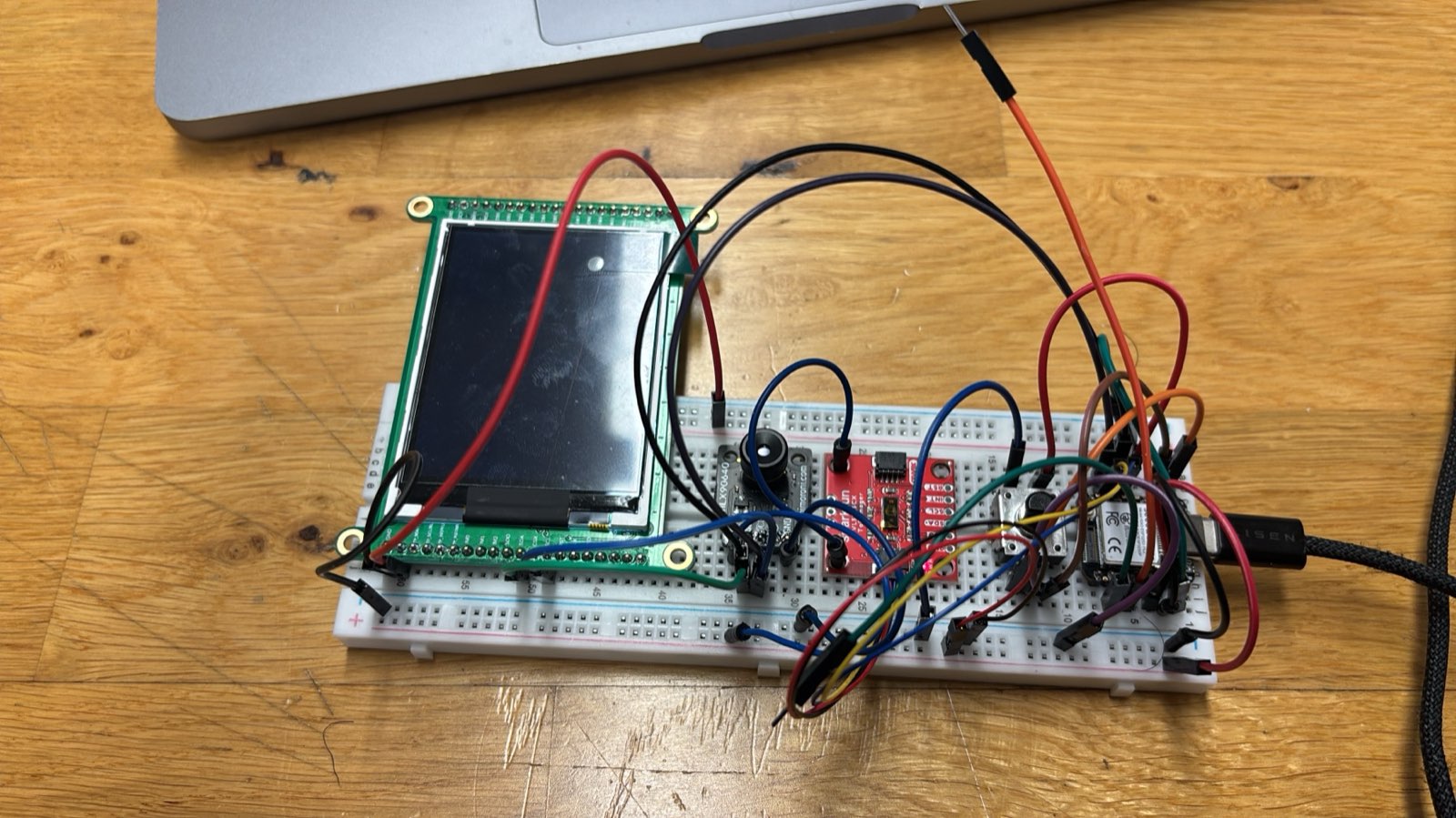
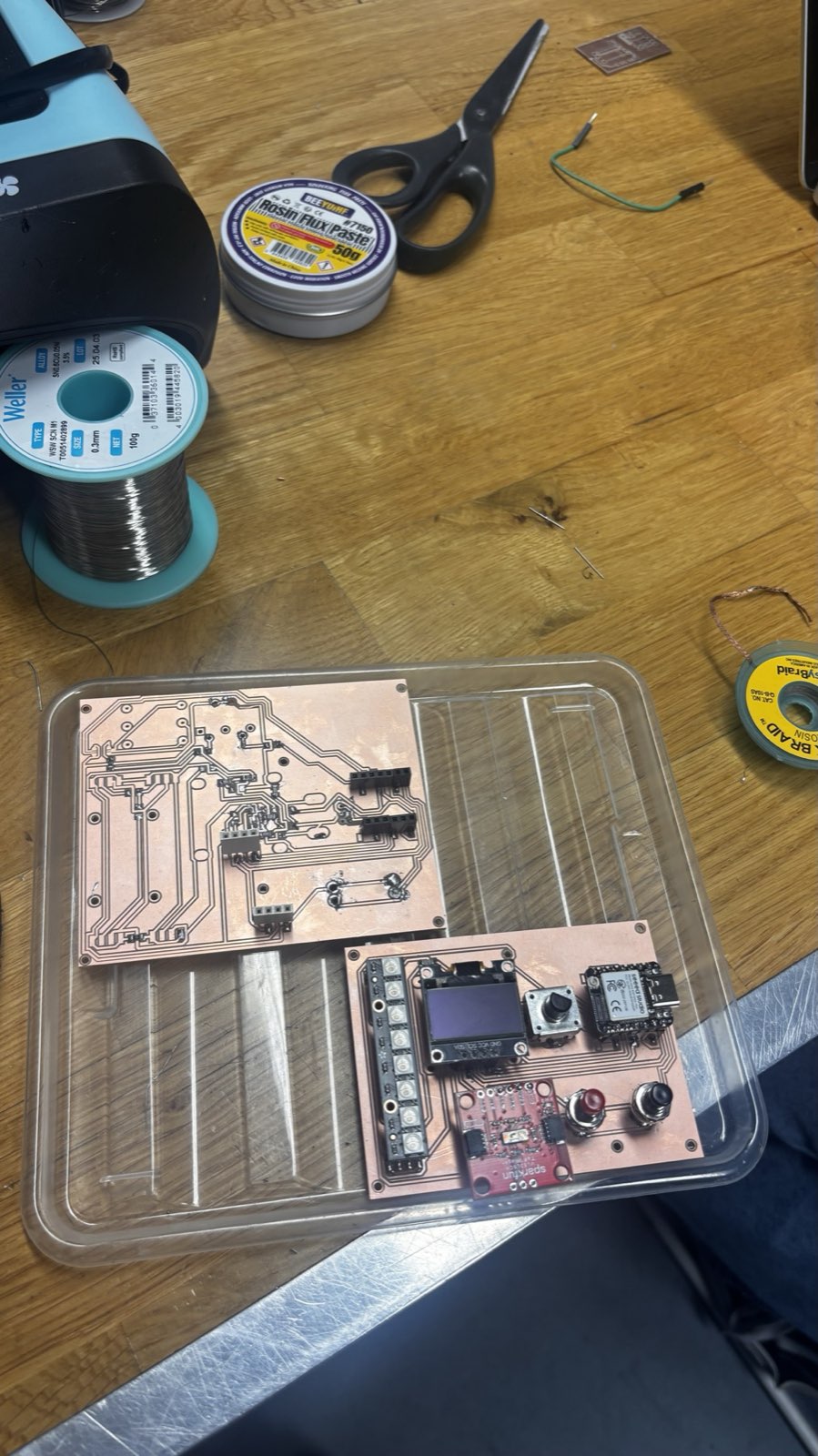
That first board didn't work out. I burned some of the components on it, and between the big screen and the extra 3.5 mm jacks there was a lot to populate and rework, so it was fiddly to work with. I simplified: I dropped the 3.5 mm jacks and the thermal camera, and swapped the Newhaven TFT for the same SSD1306 OLED I already used in the guitar: fewer parts, and a display I'd already gotten working. The Newhaven screen and the thermal camera went back to the Fablab, since the simpler receiver didn't need them. That left me with the redesigned receiver below.
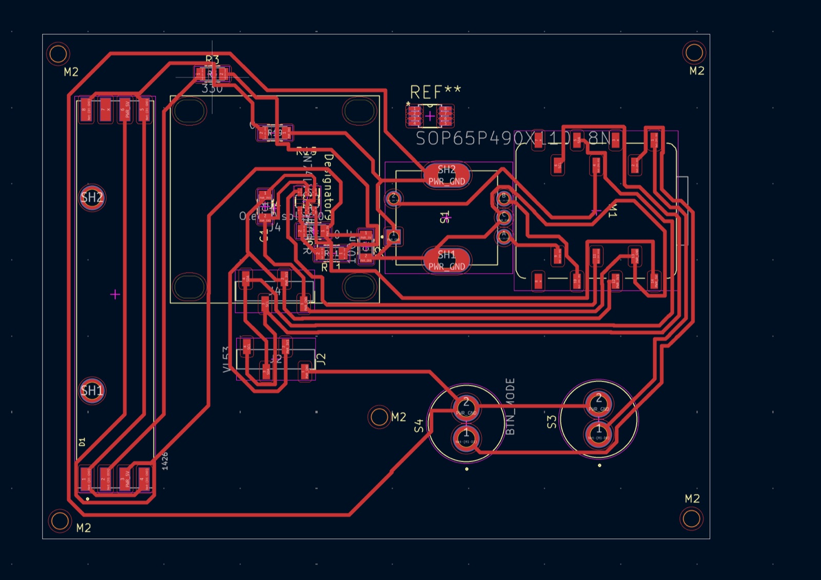
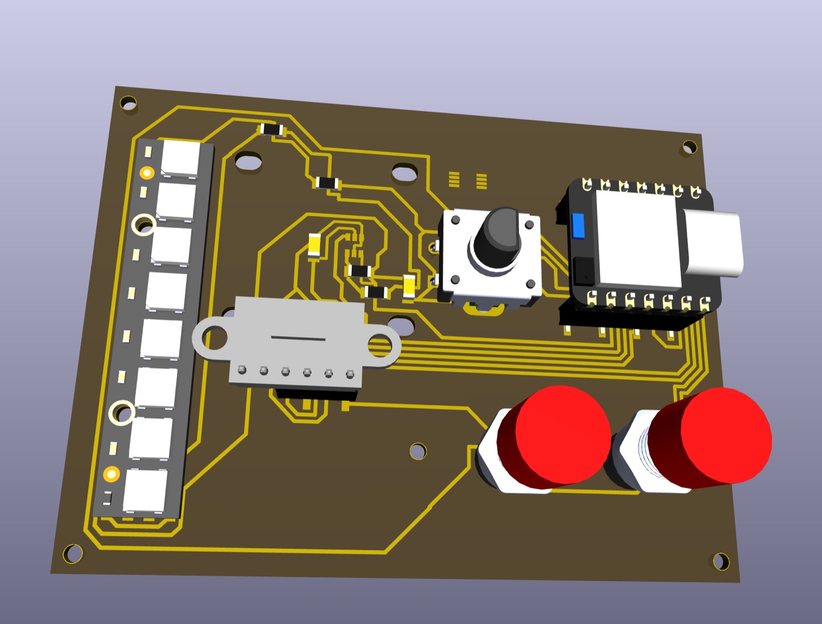
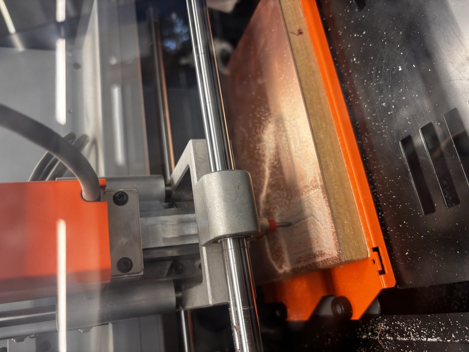
With the simpler layout settled I milled the board on the Roland SRM-20 at the Fablab.

5. Linking the Two Boards over ESP-NOW
The two boards are joined with ESP-NOW, a peer-to-peer protocol built into the ESP32. It is connectionless and does not need a WiFi network or a router. Each board only needs the other's MAC address to send short messages directly, with low latency. I first tried ESP-NOW in Assignment 10, and this project is where it earns its place.
The flow is one direction, guitar to receiver:
- The guitar reads its sensor and controls and packs the values into a small message.
- It sends that message over ESP-NOW to the receiver's MAC address.
- The receiver gets the message and turns it back into MIDI.
- The receiver routes that MIDI out: to a computer over USB, or on to connected instruments.
Splitting the work this way keeps the guitar simple (it only has to sense and send) and puts all the routing decisions on the receiver, which is the part that talks to the rest of the setup.
6. The Full System
Together the two boards make the wireless link work: the guitar on one side, the receiver on the other, and ESP-NOW carrying the messages between them so the receiver can hand them off to the computer or to instruments.
7. Reflection
The thing I'm most glad about is cutting the scope early. Trading the sequencer for a focused receiver gave me a project that goes from board design all the way to a working wireless link, rather than a bigger idea I couldn't finish.
What's left is mostly finishing work: an enclosure for the receiver, the larger TFT interface, and cleaning up the firmware on both ends. The hardware is in place and the two boards talk to each other, which was the goal for the final project.