1. How I Use Wireless Communication
Continuing on the firmware from Assignment 09 — same XIAO ESP32-S3, same hardware, but a new version of the code that adds networking on top.
The MIDI Guitar uses wireless communication in two complementary ways.
First, BLE-MIDI lets the guitar send musical messages directly to a phone, tablet,
or laptop running a synth or DAW — no cables, no dongles. The host pairs with the device advertised
as MidiGuitar and immediately starts receiving MIDI Control Change (CC20 = distance,
CC21 = velocity) and 14-bit Pitch Bend generated from the ToF sensor.
Second, WiFi in Access Point mode turns the guitar into a tiny web server for live
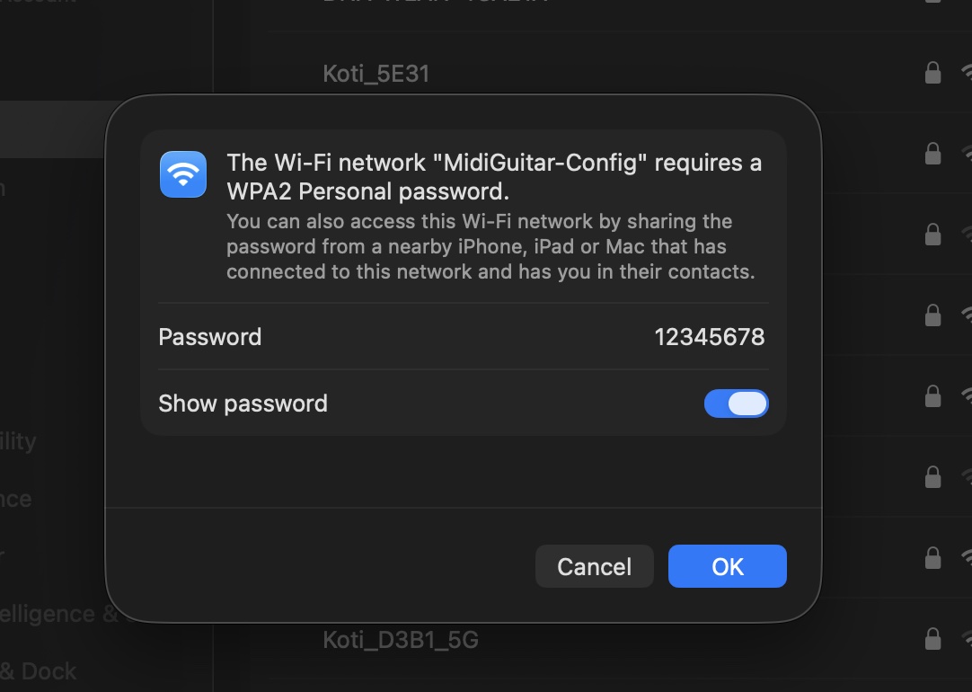
configuration. The performer triple-taps the encoder, joins the MidiGuitar-Config
network from their phone, and tweaks MIDI channel, CC numbers, sensor range, LED brightness, and
presets in a browser — no re-flashing required. Both radios share the 2.4 GHz antenna, so WiFi
stays OFF during play to keep BLE-MIDI latency under 20 ms.
2. Connecting to the Board from a Web Browser
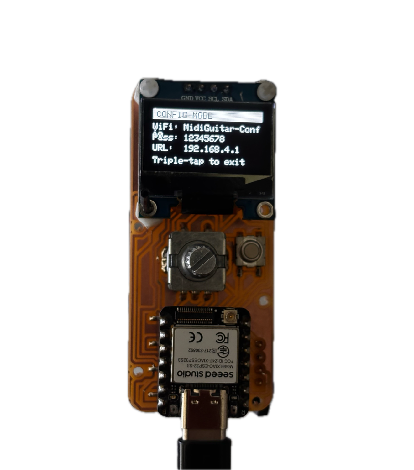
To make the board reachable from a browser, the ESP32 runs in WiFi Access Point mode: it broadcasts its own network and starts a small HTTP server on port 80. No router or internet is required — the phone connects directly to the guitar.
MidiGuitar-Config network and
opening http://192.168.4.1.WiFi.mode(WIFI_AP);
WiFi.softAP(AP_SSID, AP_PASS); // "MidiGuitar-Config" / "12345678"
IPAddress ip = WiFi.softAPIP(); // always 192.168.4.1
webServer.on("/", handleRoot); // map URL → handler
webServer.begin();
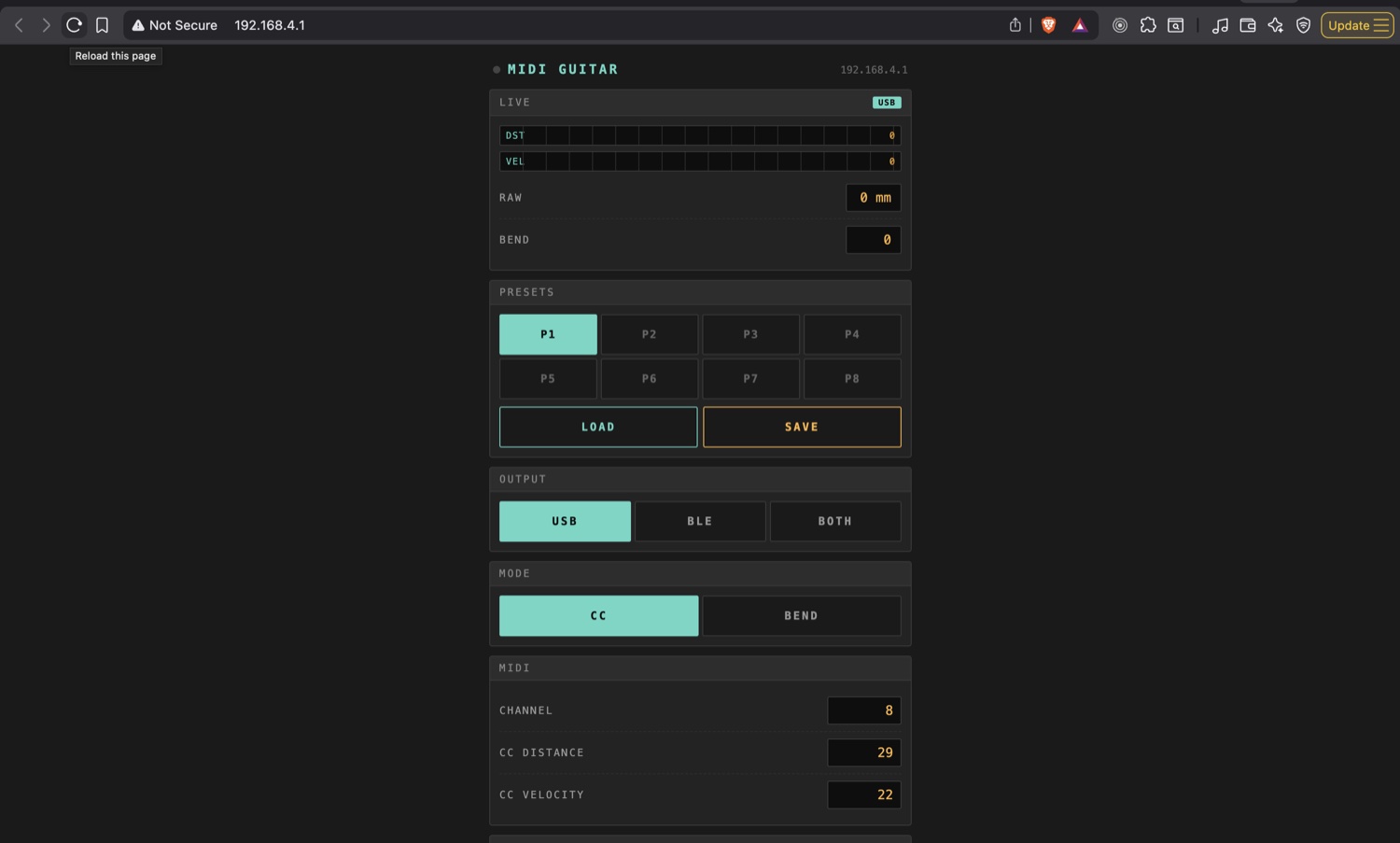
When the browser requests /, handleRoot() returns an HTML page that lives
in PROGMEM as WEB_UI_HTML. To avoid blocking the MIDI hot loop, the server is pinned
to the second CPU core via FreeRTOS:
xTaskCreatePinnedToCore(webTask, "web", 8192, nullptr, 1, &webTaskH, 0);
The user joins MidiGuitar-Config, opens http://192.168.4.1,
and the configuration page loads.
3. Sending Data To the Board
http://192.168.4.1.
Sending data to the board uses simple HTTP GET requests with query string
parameters. The web UI's JavaScript fires fetch('/api/set?k=ccd&v=42')
whenever the user moves a slider, where k is the setting key and v is the
new integer value. The handler parses the arguments, validates the key, and writes the value to the
matching runtime variable:
static void handleApiSet() {
    const String &k = webServer.arg("k");
    long v = webServer.arg("v").toInt();
    const Setting *s = settingByKey(k.c_str());
    if (!s) { webServer.send(400, "text/plain", "bad key"); return; }
    settingSet(*s, v);
    webServer.send(204);     // 204 = success, no body
}
Changes propagate instantly: the OLED redraws, the LED ring updates colour, and the new value is
queued for non-volatile (NVS) save two seconds later. Presets save and load via
/api/preset?slot=N&op=save|load the same way.
4. Receiving Data From the Board
The browser receives data from the board by polling two JSON endpoints. /api/state
returns the full current configuration once at page load; /api/live returns real-time
sensor readings several times per second. Both are built with snprintf into a fixed
char[] buffer rather than the String class, so the heap stays stable
during long sessions.
static void handleApiLive() {
    char buf[120];
    snprintf(buf, sizeof(buf),
        "{\"d\":%d,\"v\":%d,\"b\":%d,\"mm\":%d,\"c\":%u,\"bp\":%u}",
        liveDist, liveVel, liveBend, (int)(ema >= 0 ? ema : 0),
        bleConnected ? 1u : 0u, bypassed ? 1u : 0u);
    webServer.send(200, "application/json", buf);
}
The keys are abbreviated (d = distance CC, v = velocity, b =
pitch bend, mm = raw millimetres) to keep packets small. The page parses each response
and updates the on-screen meters, letting me watch the ToF sensor live and tune the distance range
visually.
5. Wired Communication — I²C
Wired board-to-board communication isn't new for me on this course — back in
Assignment 08 (MIDIHost2Host) I built a small bridge
where two XIAO RP2040s talked to each other over UART (hardware
Serial1, TX/RX at 31250 baud, classic MIDI), with one side bridging to USB MIDI. So
the "wired protocol between two boards" piece of this assignment was already covered there.
This time the wired side is I²C, which is a different problem: instead of a
point-to-point serial link between two microcontrollers, I have one microcontroller (the
XIAO ESP32-S3) talking to two peripherals on the same two-wire bus — a
VL53L1X time-of-flight sensor at address 0x29 and an
SSD1306 OLED display at 0x3C. Both share the SDA/SCL pins on the
XIAO ESP32-S3 (GPIOs 5 and 6), so a single two-wire bus carries everything — that is the whole
point of I²C.
#define I2C_SDA   5     // XIAO D4 → sensor SDA + OLED SDA
#define I2C_SCL   6     // XIAO D5 → sensor SCL + OLED SCL
#define I2C_FREQ  400000

Wire.begin(I2C_SDA, I2C_SCL, I2C_FREQ);
sensor.begin(Wire);
oled.begin(SSD1306_SWITCHCAPVCC, OLED_ADDR);
At boot the firmware scans every address from 1 to 126 and prints every ACK to the serial console. This is both a sanity check during bring-up and deliberate warm-up traffic — the SSD1306 clone on my PCB refuses its init sequence unless the bus has already seen activity:
for (uint8_t a = 1; a < 127; a++) {
    Wire.beginTransmission(a);
    if (Wire.endTransmission() == 0) Serial.printf("[I2C] 0x%02X ACK\n", a);
}
6. Reference — Endpoints & Source
The complete WiFi + web-server code lives in
tof_midi_v5.ino between the comment markers
// ─── WiFi config mode ─── (line ~413) and the end of
exitConfigMode() (line ~549), plus the #include <WiFi.h> /
#include <WebServer.h> block near the top.
Download
tof_midi_v5.ino — the full firmware sketch (BLE-MIDI + WiFi AP + web server +
I²C sensor/OLED).
| Endpoint | Method | Purpose |
|---|---|---|
/ | GET | Serve the configuration HTML page |
/api/state | GET | Read full settings as JSON |
/api/live | GET | Read live sensor values as JSON |
/api/set?k=&v= | GET | Update one setting |
/api/preset | GET | Save / load a preset slot (0–7) |