0. The Idea — A MIDI Guitar Controller
I want to turn a Squier Mustang into a MIDI controller — keep everything but add a nervous system on top: using a ToF sensor as my input send that data as MIDI over USB and Bluetooth into anything I have running (Ableton, Norns, a synth). The brain is a Seeed XIAO ESP32-S3 Sense, picked for the Bluetooth + USB capabilities and because it's tiny enough to hide under the pickguard.
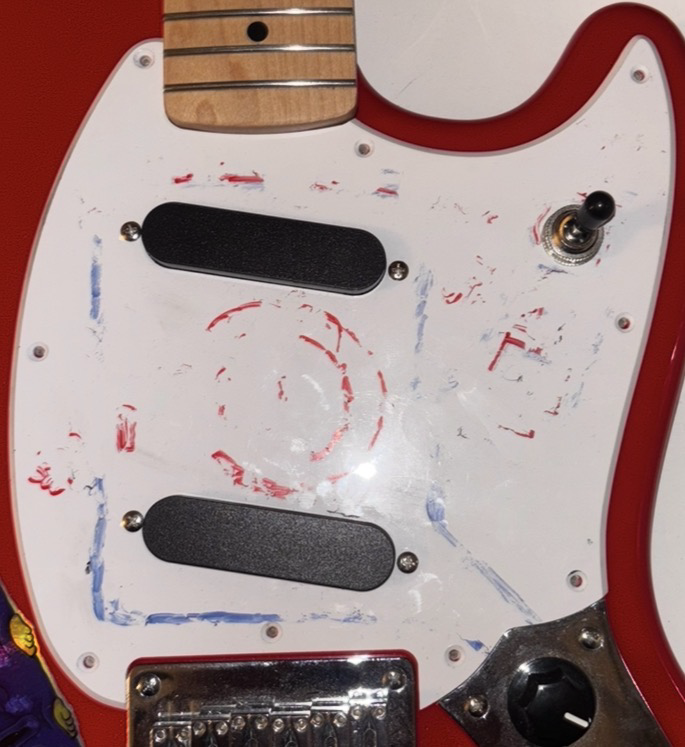
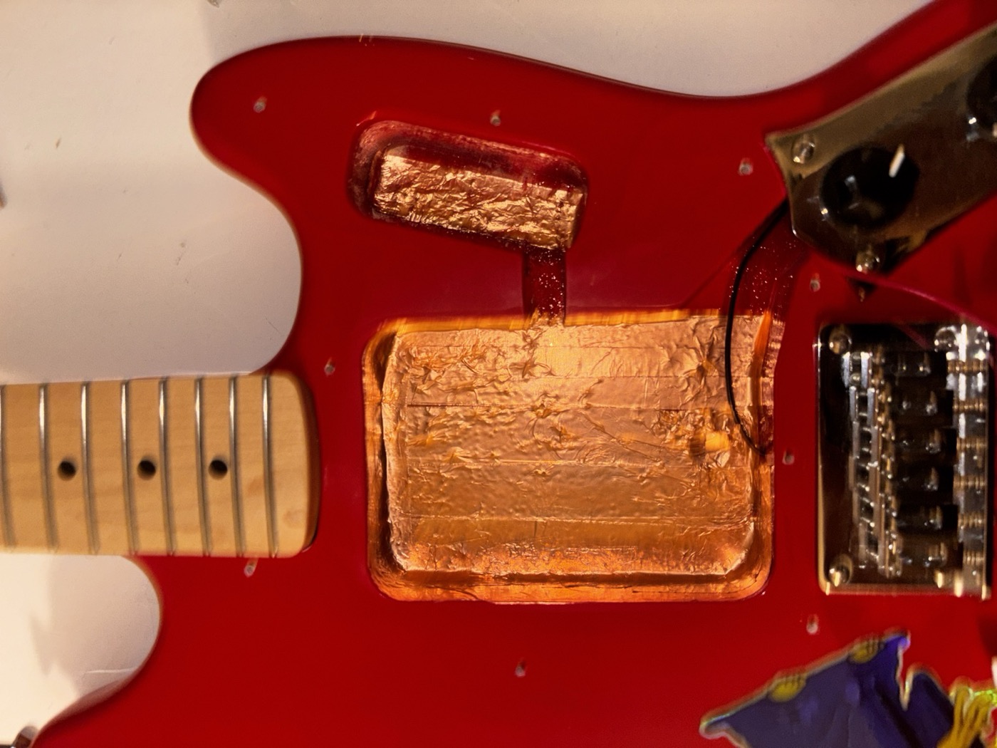
Before any of the electronics could go in, I had to deal with noise of guitar pickups. Stuffing a microcontroller and a strip of addressable LEDs inside a guitar is a great way to make a hum factory, so I lined the cavity with copper foil tape and tied it to the existing ground.
1. Input Devices
VL53L4CD — Time-of-Flight Sensor
The VL53L4CD is a tiny (LiDAR) laser-based distance sensor that bounces an infrared pulse off anything in front of it and measures how long the photons take to come back. It talks over I²C and gives you distance in millimeters, super fast. I chose this over the VL53L1X because it has a wider field of view and better performance. I'm using the SparkFun Qwiic breakout because it makes the wiring on a breadboard easy for prototyping but later I will properly solder the components through cables.
The reason I want it is to get continuous expression while I'm playing — wave my picking hand over it and it sends to CC channels. Think of it as an expression pedal that lives on the guitar itself.
Rotary Encoder
A standard mechanical rotary Bourns encoder with a push-switch, used as an input control for menu navigation on the OLED. and the push button is really handy imo.
Push Button
One button next to the encoder, used to switch for extra menu options and navigation. The original plan was to use a TTP223 capacitive touch chip with a copper pad under the pickguard — that's still on the list for the final version — but for the working prototype a normal mechanical button was faster to get going.
2. Output Devices
0.96" OLED — I²C
This is a tiny SSD1306-based OLED, 128×64 pixels, talking to the ESP32-S3 over the same I²C bus as the ToF sensor. It will be my output device for a UI to control and see the data being sent from the device. I drew the UI layout on paper first and then mocked it up in Adafruit_GFX — keeping it readable at a glance is the priority for such a tiny display, yet it fits perfectly in the electronics cavity of the guitar.
Neopixel Ring — 16 LEDs
The Neopixel ring is the other output device. It sits in the middle of the pickguard. And it's basically a halo of addressable LEDs, controlled with a single data line. I want it to give me peripheral feedback — color shifts as the ToF distance changes, a chase animation when I switch banks. Visual stuff that tells me what the instrument is doing without me having to look down at the screen.
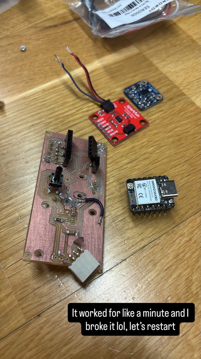
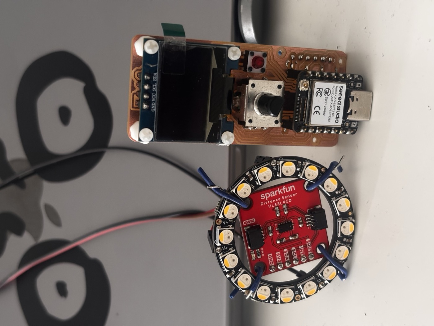
3. The Software Side — What Actually Works
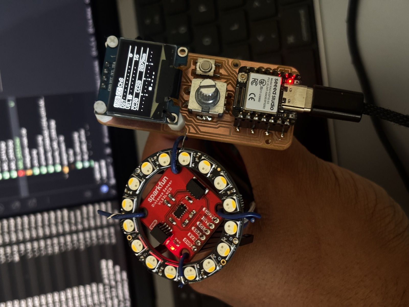
Okay, before I get into the part where I am stuck (the PCB milling), the software side of this project works but I still need to print one last board. I had a fully functional breadboard prototype where the XIAO ESP32-S3 reads the ToF sensor, the encoder and the button, drives the OLED and the Neopixel lights up, and as an extra it sends real MIDI CC messages over USB to my laptop. I can open Ableton, hover my hand over the sensor, and the filter cutoff moves. So the inputs and outputs side of the assignment is covered in the code.
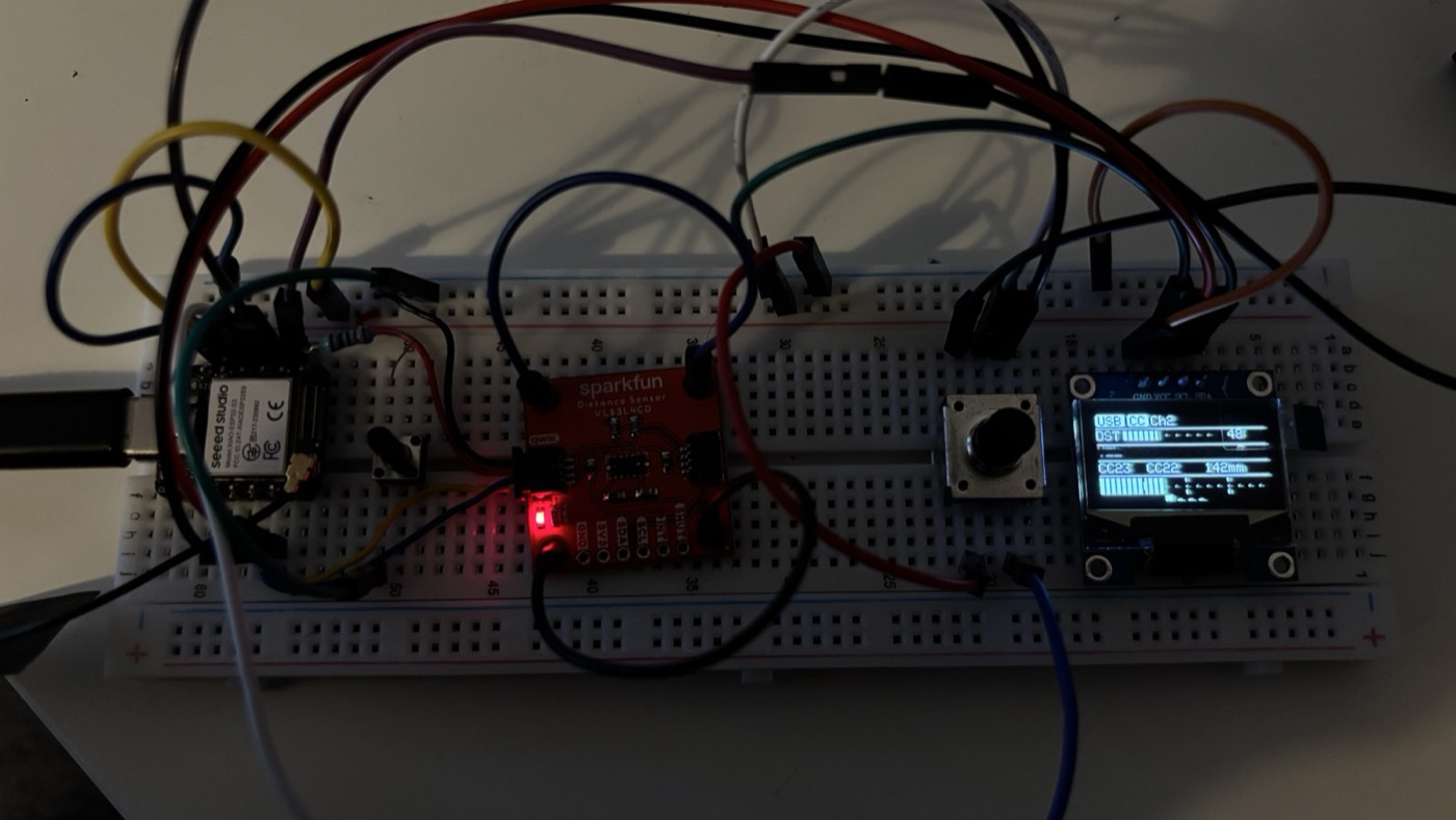
Watching the OLED update in real time while I'm scrolling the encoder is honestly one of the more satisfying things I've made on this course. Every input and every output is doing its job, and the firmware glues them together with a small UI: bank select, CC select, channel select, confirm.
4. Designing the Board in KiCad
With the breadboard version doing what I wanted, I sat down in KiCad and started laying out the schematic for a real PCB. The XIAO ESP32-S3 sits in the middle on a socketed footprint (so I can pop it out if I fry the board as it has happened), with everything else fanning out: I²C bus going to the OLED and the ToF sensor, the Neopixel data line on its own GPIO, the encoder and the button each on their own pins, and the power rails routed as wide as possible to help minimize voltage drop.
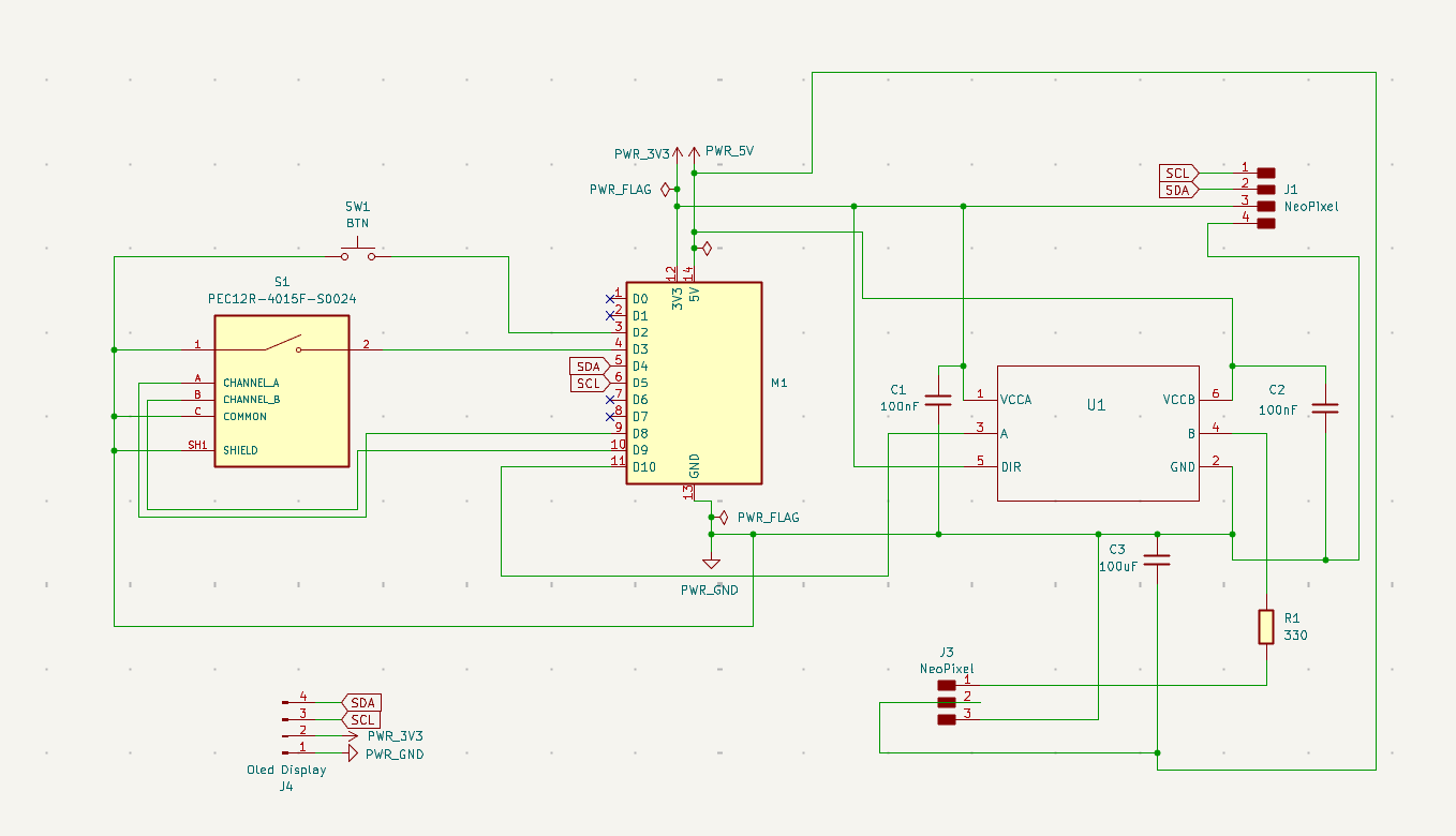
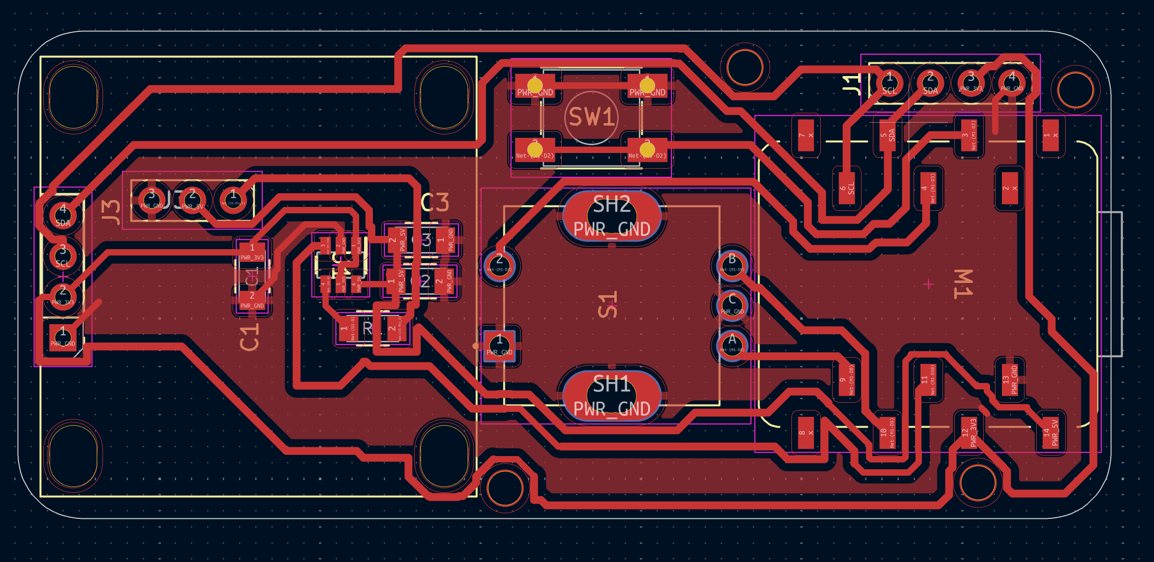
I tried to keep the board small enough (~70mm x 30mm) to fit under the pickguard without fighting the existing routing for the pickups too much. Most of the trace work is on a single layer because milling double-sided boards on the SRM-20 is a whole separate adventure I wasn't ready to take on for these four weeks or so.
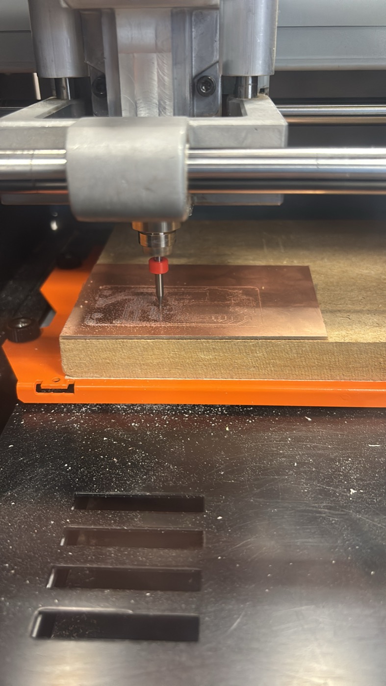
5. Six Boards Later — Fighting the SRM-20
Okay, this is the part I have to be honest about: I did not finish this assignment on time, and the reason is that I milled six versions of this PCB on the Roland SRM-20 and none of them came out the way I wanted. I learned a lot, but I also burned through a lot of copper and a lot of evenings.
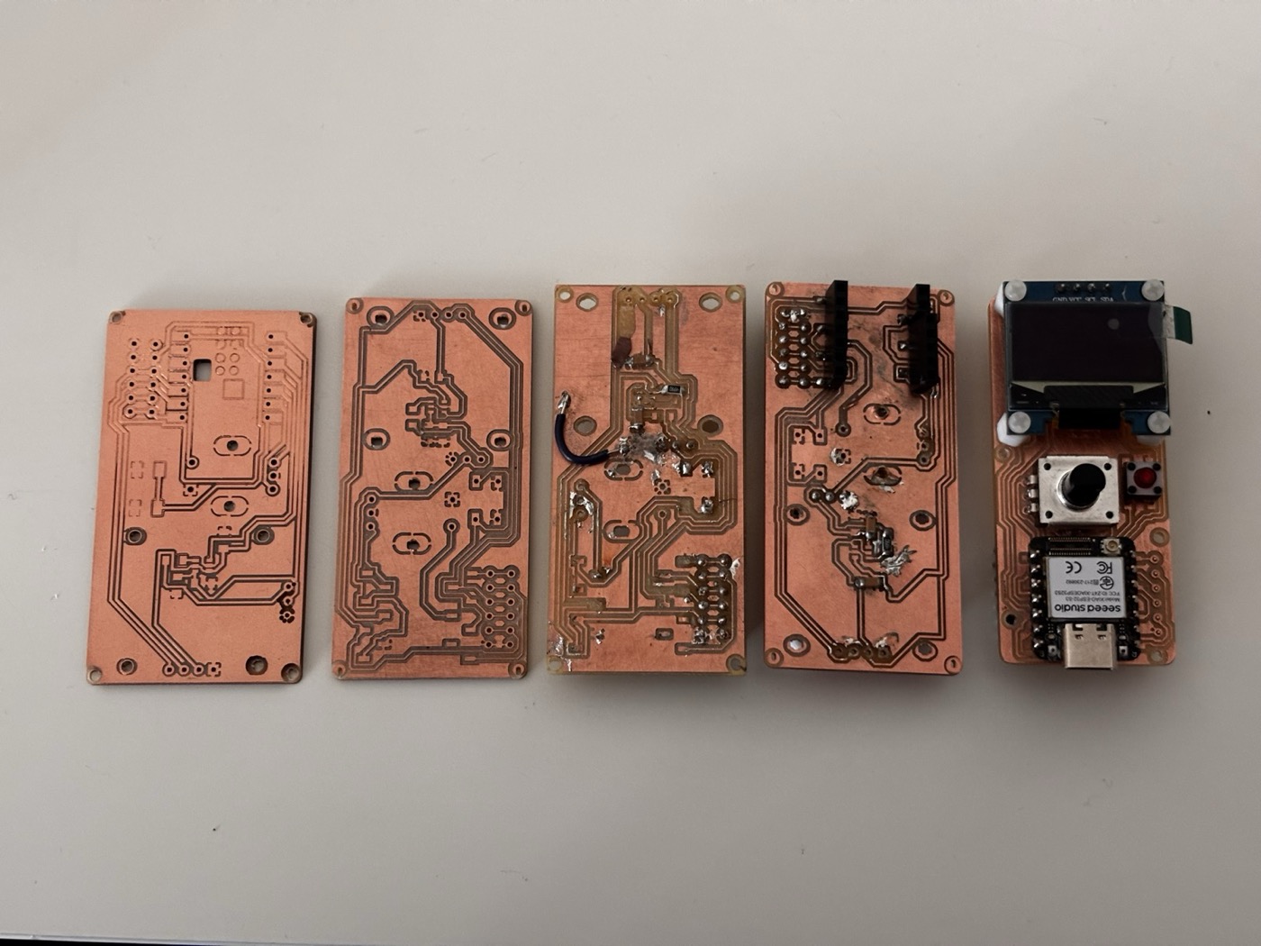
The main fight was with trace width. My first board had traces that were too thin — they came out fine on the design but the isolation cuts on either side ate into them, and a couple of traces straight up disappeared. So I bumped the widths up. Then the pads on the XIAO footprint got too close to each other and the mill couldn't isolate between them at all, so it just skipped those cuts and I ended up with shorts everywhere. Bumped the pad spacing. New problem: now the board doesn't fit where I wanted it to fit.
Somewhere around board three or four I started getting Z-axis issues — the bit was either floating above the copper and not cutting through, or digging in too deep and tearing chunks out of the substrate. I re-leveled the bed multiple times and re-zeroed the bit, and it would work for one board and then drift again. By the time I got to board six the geometry was finally right but the cut quality was still inconsistent enough that I didn't fully trust the traces.
Lessons learned:
- Trace width matters more than I realized — for the SRM-20 with the bits we have, ~0.4 mm is roughly the floor.
- Isolation width (the gap between traces) is a separate parameter and it has to match what the bit can physically cut.
- Re-leveling and re-zeroing the Z axis between every single board is non-negotiable, even when it feels paranoid.
- Test cuts on a scrap piece before committing the real design saves so much time.
- The copper layer "de-glues" from the substrate way more easily than I expected — once a thin trace lifts off the FR-1, there's no saving it but jumper cables.
- Don't change three things at once between iterations. I did this constantly and then couldn't tell what fixed what.
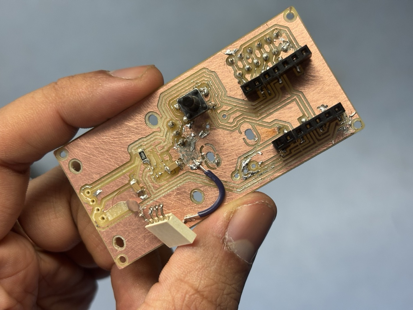
6. The Final Board
This is the last board I milled. The geometry is finally right, the trace widths are in a safer zone, but the cut quality is still inconsistent and I don't trust it enough to put it in the guitar. I might print a PCB in the future with a different method, but for now this is the final version of the design that I have. with this last board I learned to desolder smd components with the the pinch tool and also the 5mm traces are more reliable than the 4mm ones. I also added a few extra M2 holes for mounting the board to the guitar pickguard.
7. What's Next — xTool + Bungard BEL
After the sixth board I sat down and admitted that subtractive milling on the SRM-20 isn't the right process for this design. The traces I want are too thin, the FR-1 substrate keeps de-laminating around fine cuts, and the Z-axis drift is eating my time. So the plan for finishing the project is to switch toolchains.
- xTool — using the laser to either etch a resist on copper-clad for chemical etching, or to cut a vinyl mask. Both routes give me cleaner edges than the mill at the trace widths I actually need.
- Bungard BEL — re-running the same PCB edges to work on the xtool, this is an extra step but will make higher quality boards I hope.
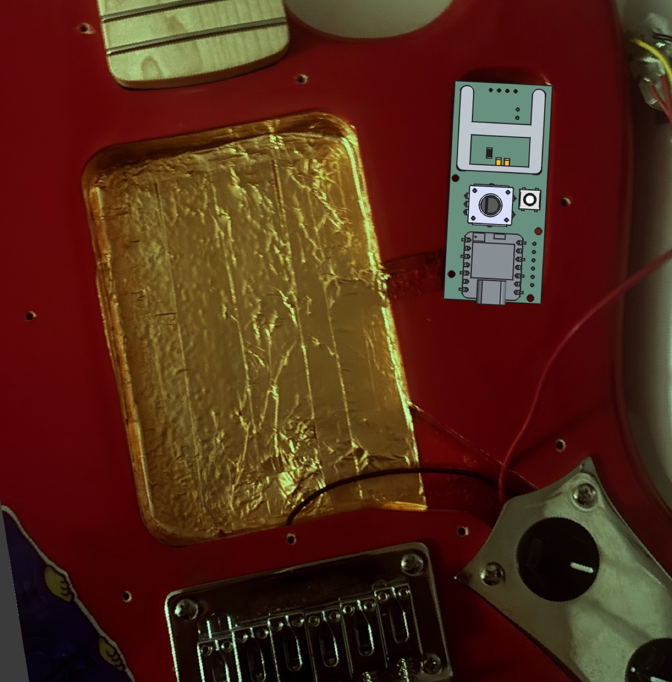
8. What It'll Look Like When It's Done
To keep myself motivated I overlaid the board outline on a photo of the actual guitar body — OLED on one side, Neopixel ring in the center, ToF sensor close to the pickups, encoder and button on the other side. This is the positioning I'm aiming for designing the pickguard that will hold everything together. I know this is extra but I just wanted to showcase the full idea of this project, which extends beyond the inputs and outputs assignment (and maybe why I am also late to finish it).
9. Project Files
I documented everything in a private GitHub repo as I went along — messy commit history with all the failed board iterations and the firmware evolution included. Download the full project archive.