13 — Molding and Casting

1. How I Will Use Molding and Casting

Both halves of my final project have a rotary encoder on them: the transmitter routed into the guitar body, and the receiver that forwards the MIDI to a computer. Both are still wearing the generic caps that came with the encoders.

I want a matching pair instead, which is what makes casting the right process. One master, one silicone negative, then as many identical knobs as I need.

I would rather have them in something rubberized so they grip under a finger. I am not sure the Fablab stocks a casting material like that, so plastic resin is the fallback and would be fine.

2. Designing the Knob

A short cylinder with a blind bore for the encoder shaft, built in one Part Design body: a single Pad, then two Chamfers and three Fillets so no sharp edge is left on it. Sharp edges are where silicone tears and where resin traps air.

The model is driven from a Spreadsheet, same as the table in Assignment 11, so the knob can be resized without reworking the features.

3. Modelling the Negative Mold

The idea is simple: subtract the knob from a block. What made it slow is that Part Design does not let one body reference another body's geometry.

First attempt was a second body in the same document, sketched against the knob.
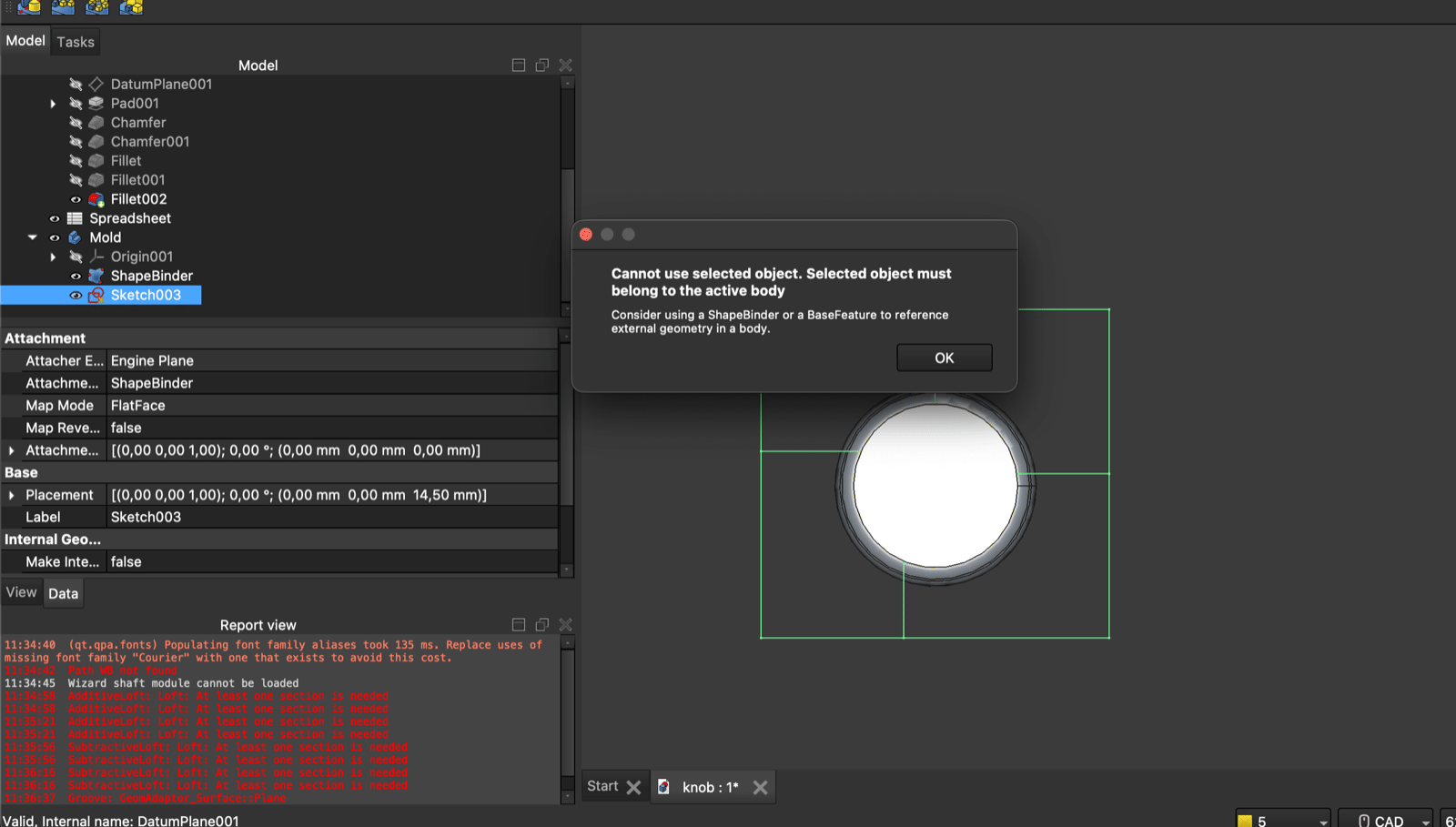
FreeCAD dialog reading Cannot use selected object, selected object must belong to the active body, with the Mold body and a ShapeBinder visible in the model tree
Sketch003 in the Mold body, rejected: the selected object has to belong to the active body. Failed Loft and Groove attempts in the report view.

The dialog suggests a ShapeBinder, which copies external geometry into the active body. But it brings in a face or an edge, not the solid, so the profiles I derived from it were open. Padding an open profile gives Wire is not closed.
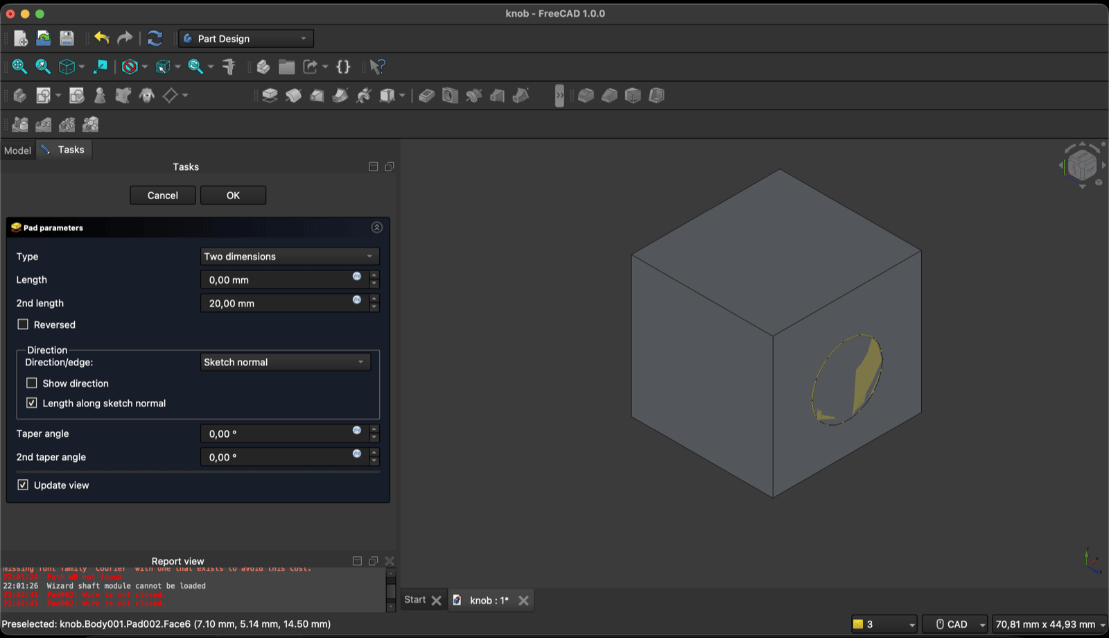
FreeCAD Pad parameters dialog set to Two dimensions with a 20 mm second length, applied to a sketch on the face of the mold block, with Wire is not closed errors in the report view
Pad set to Two dimensions, 20 mm. The yellow sliver on the block face is the profile that never closed.

Next was Up to face: pad the block and let it stop against the knob's surface. That is the operation I wanted.
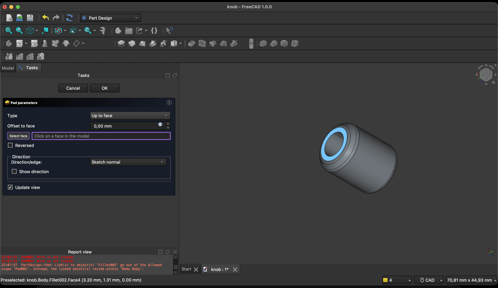
FreeCAD Pad parameters dialog with type Up to face and an empty Select face field, with the filleted knob shown alone in the 3D view
Up to face with the target still empty. The knob with its chamfers and fillets applied.
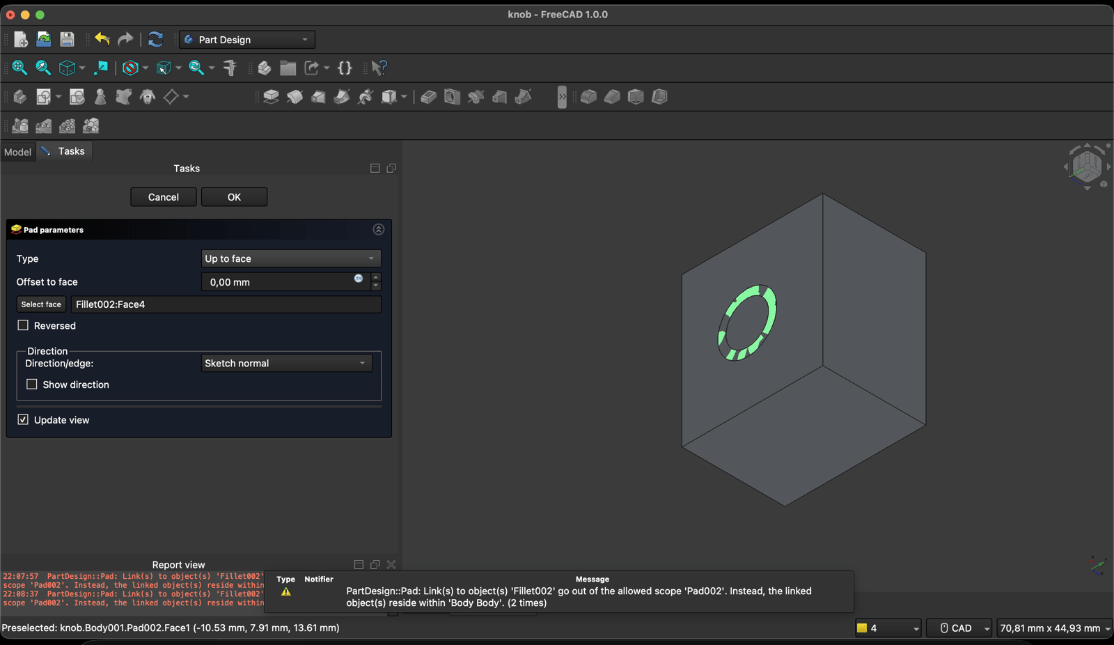
FreeCAD Pad parameters dialog with Fillet002:Face4 selected as the target face and a warning that links to Fillet002 go out of the allowed scope Pad002
Fillet002:Face4 accepted into the field, then flagged: the link goes out of the allowed scope Pad002.

Picking a face from another body fills the field in and then fails on recompute. A feature can only reference geometry inside its own body.
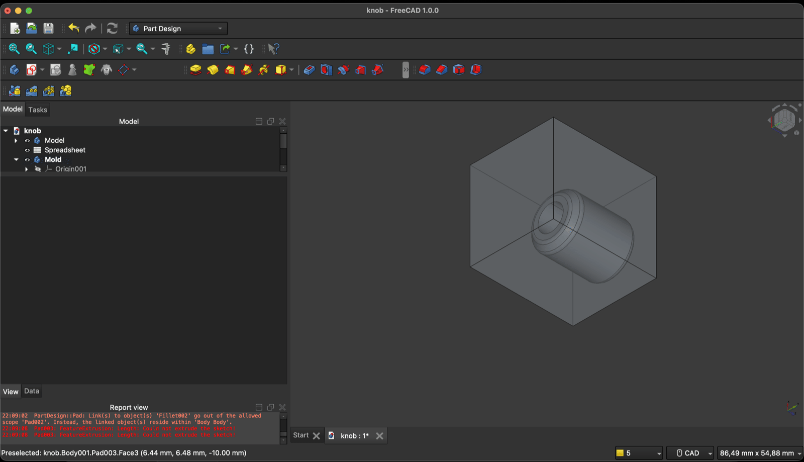
FreeCAD 3D view showing the knob positioned inside a transparent rectangular mold block, with Could not extrude the sketch errors in the report view
Knob positioned inside the block, still not a mold. Could not extrude the sketch in the report view.

What worked was dropping cross-body references entirely: build the block as its own body (MoldBase), make a Clone of the knob, and subtract it with a Part Design Boolean set to Cut. The Clone is a real solid inside the target body, so nothing reaches outside.
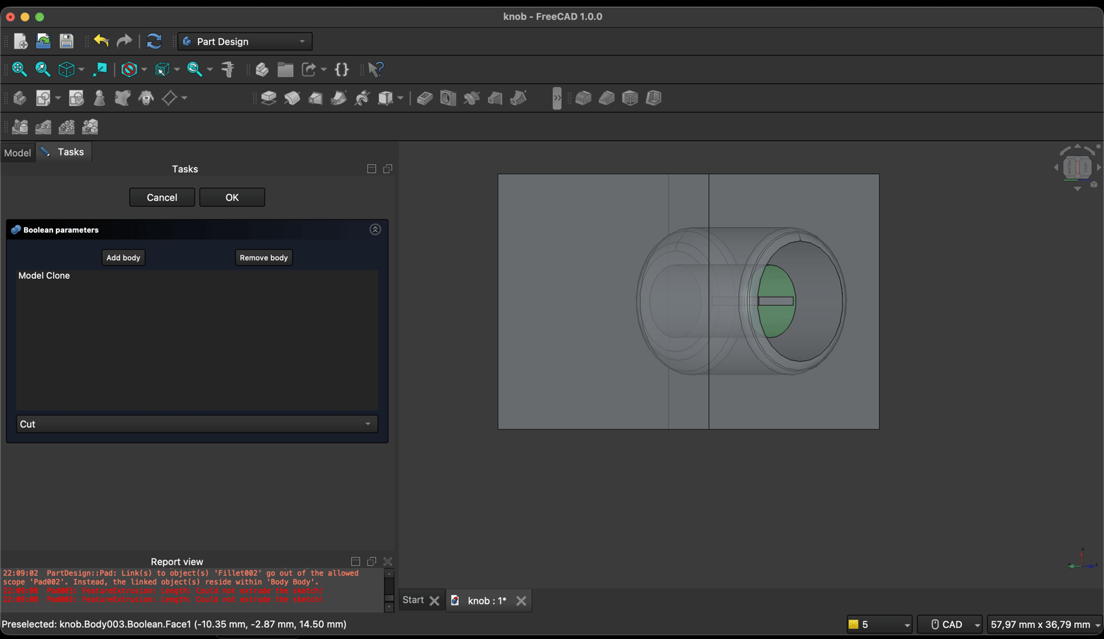
FreeCAD Boolean parameters dialog listing Model Clone as the body to subtract with the operation set to Cut, shown over a section view of the knob inside the block
Boolean set to Cut, with Model Clone as the body being subtracted. Section view through the knob and the block.
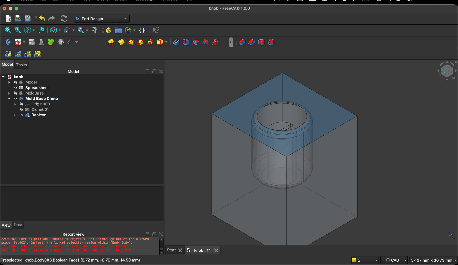
FreeCAD 3D view of the finished mold block shown transparent, with a clean cylindrical knob-shaped cavity cut through the top face
The cavity cut into the block. Tree order: MoldBase, Clone001, Boolean.

The Clone stays linked to the original, so the cavity is still parametric. Changing the knob updates the cavity in one recompute.

The cavity walls have no draft. That is fine for silicone, which flexes off the master, but a rigid mold milled straight from this block would need a degree or two of taper to release.

4. Fitting the Mold to the Stock

The mold block on its own is not enough to machine. The mill needs the wax stock around it, and the block needs to sit in the middle of that stock. So the last body is Stock Base: a ShapeBinder of the mold's face, a rectangle sketched around it, and a Pad out to the stock thickness.
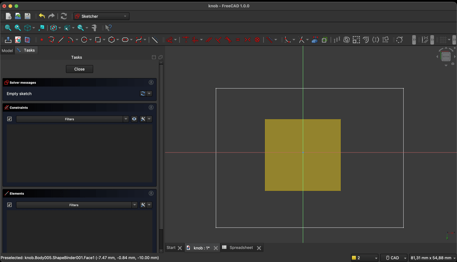
FreeCAD Sketcher with an empty new sketch, a yellow highlighted face in the 3D view, and the status bar reading Preselected knob.Body005.ShapeBinder001.Face1
New sketch opened on the ShapeBinder. Solver messages: Empty sketch, status bar: knob.Body005.ShapeBinder001.Face1.

The rectangle went in at 110 by 88 mm, the footprint of the wax block. Constraining it took a few passes.
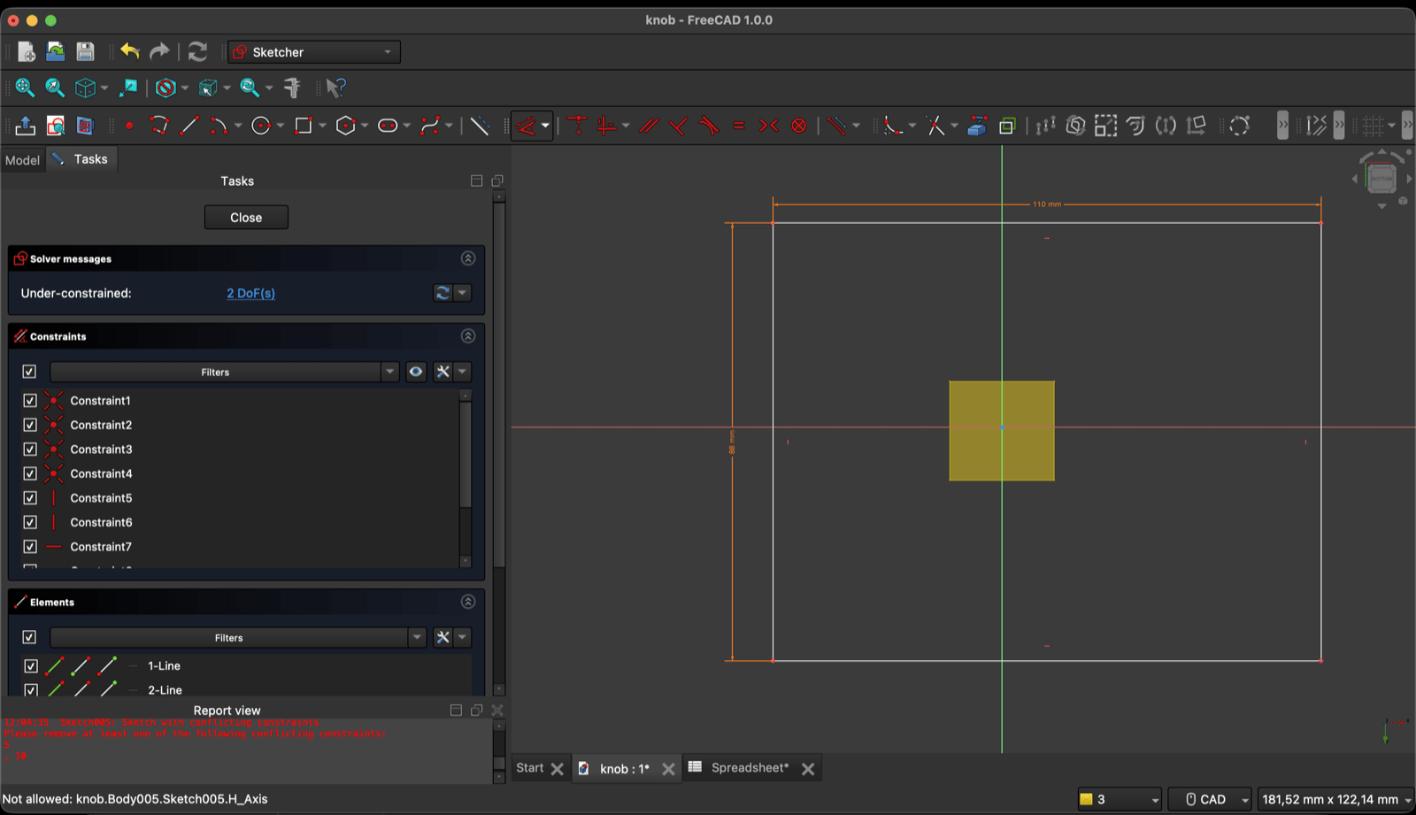
FreeCAD Sketcher showing a rectangle dimensioned 110 mm by 88 mm around a smaller highlighted face, solver reading Under-constrained 2 DoF, with conflicting constraint errors in the report view
Rectangle dimensioned 110 and 88 mm. Solver: Under-constrained: 2 DoF(s). Report view: Sketch with conflicting constraints, pointing at 5 and 10.

To centre the block I ran lines from each side of the rectangle to the corresponding side of the mold face and set the opposite pairs equal. Two equalities, one per axis, and the block is centred without a single hard-coded offset. The first attempt piled on far too many constraints.
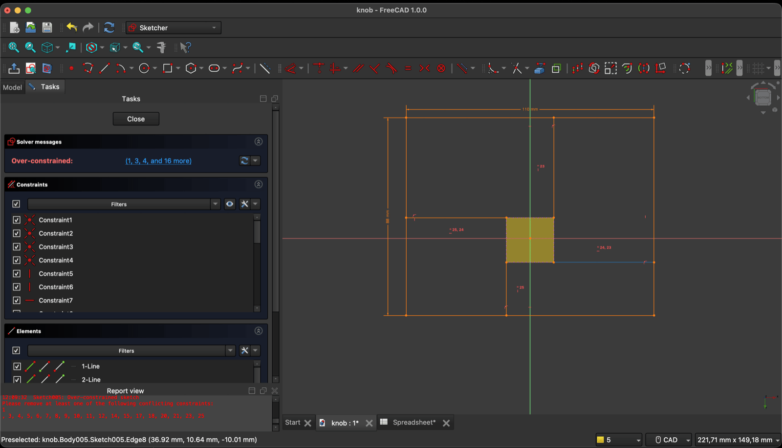
FreeCAD Sketcher with orange centring lines between the outer rectangle and the inner face, equal constraint labels, and the solver reading Over-constrained in red
Centring lines in place with the equal-constraint labels = 23, = 24, = 25. Solver: Over-constrained: (1, 3, 4, and 16 more).
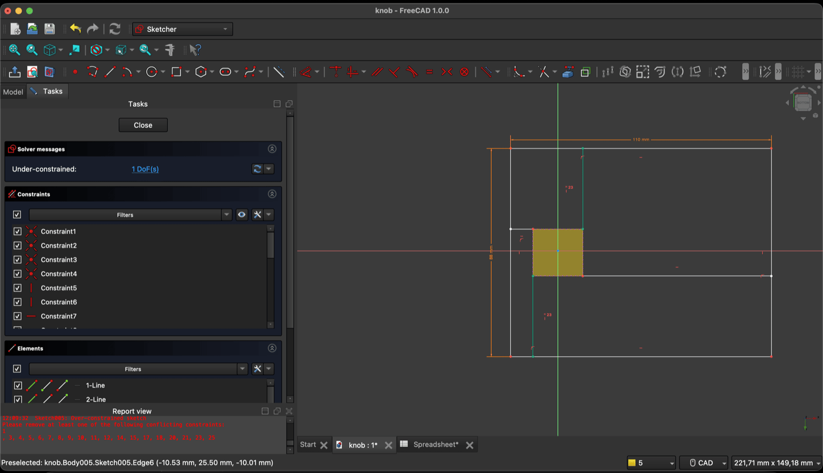
FreeCAD Sketcher after removing constraints, solver reading Under-constrained 1 DoF, with two equal constraint labels reading 23 on the vertical centring lines
Constraints stripped back. Solver: Under-constrained: 1 DoF(s), with the vertical pair still tied together as = 23.
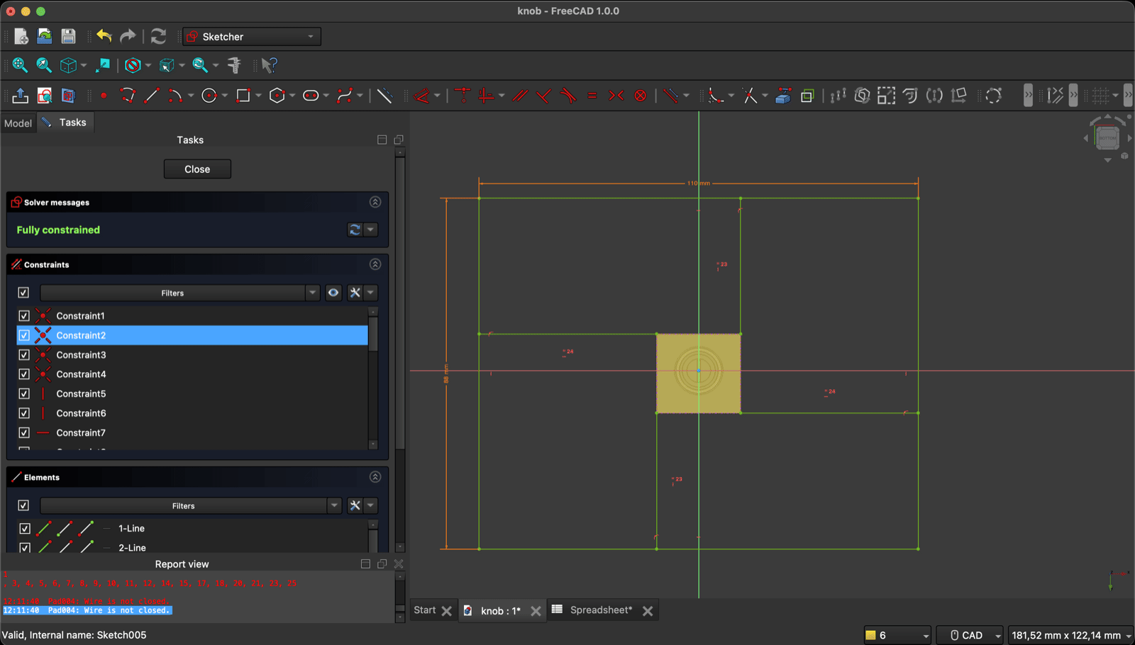
FreeCAD Sketcher with the outer rectangle and centring lines drawn green, all four gaps labelled with equal constraints, and the solver reading Fully constrained in green
Solver: Fully constrained. All four gaps carry an equality, = 23 vertically and = 24 horizontally. The knob's circles are visible in the bound face.

Those four lines are geometry the Pad would try to use, so they get toggled to construction. They still hold the sketch together and the Pad ignores them.
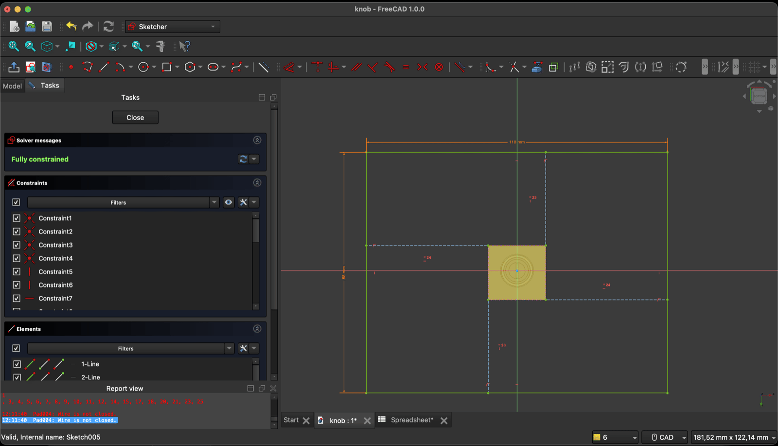
FreeCAD Sketcher with the same fully constrained sketch, the centring lines now drawn as blue dashed construction geometry
The same sketch after the toggle: centring lines now blue and dashed, the outer rectangle still green and fully constrained.

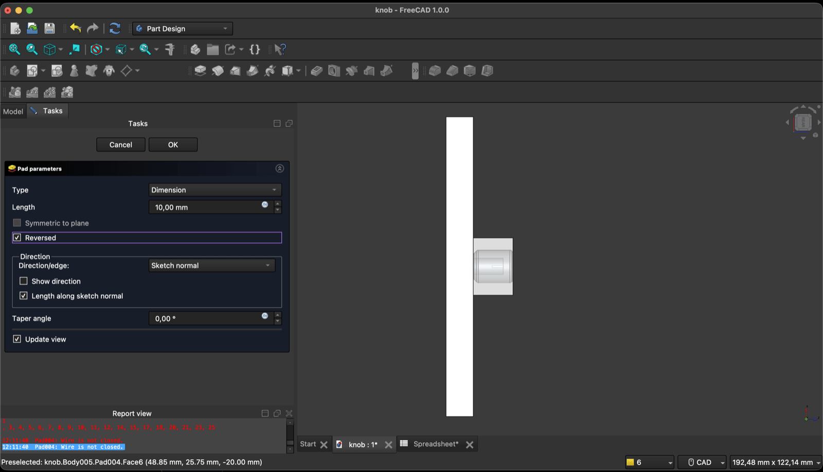
Then the Pad, which came out on the wrong side of the sketch plane.
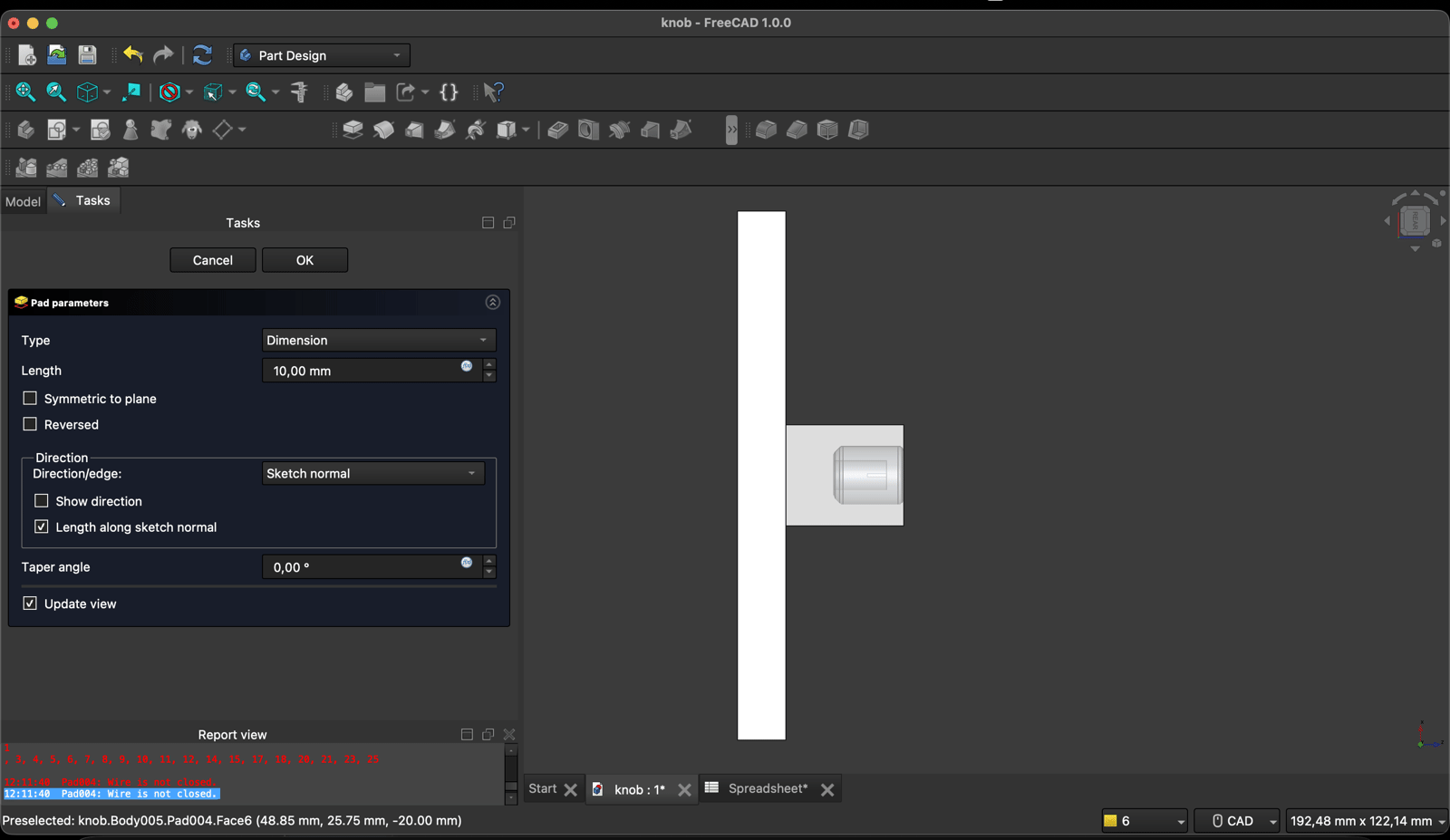
FreeCAD Pad parameters dialog with type Dimension and length 10 mm, the padded slab shown edge on in the 3D view with the mold block sitting off to one side of it
Pad at 10 mm, Reversed unchecked. Edge-on view: the slab grows away from the mold block instead of around it.
FreeCAD Pad parameters dialog with the Reversed checkbox ticked and highlighted, and the mold block now on the other side of the slab in the 3D view
Reversed ticked. Same 10 mm, the other way.

The length itself is not typed in. It is bound to the spreadsheet, same as everything else on this part, so a different block of wax is a cell edit rather than a remodel.
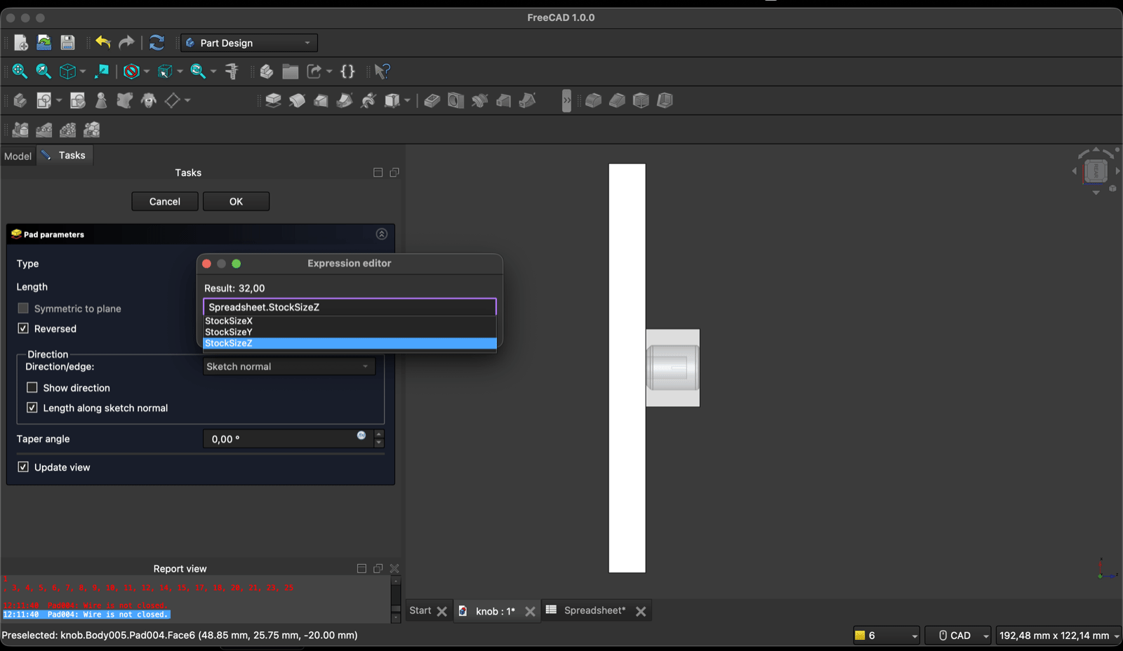
FreeCAD Expression editor over the Pad length field containing Spreadsheet.StockSizeZ, result 32, with an autocomplete list showing StockSizeX, StockSizeY and StockSizeZ
Expression editor on the Pad length: Spreadsheet.StockSizeZ, Result: 32,00. The autocomplete lists the three cells I added, StockSizeX, StockSizeY, StockSizeZ.
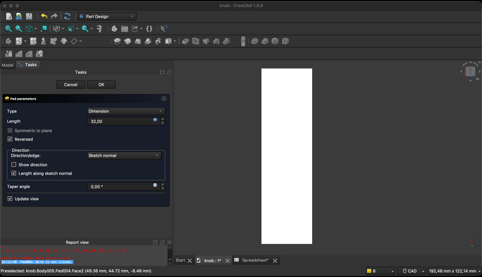
FreeCAD Pad parameters dialog with the length field showing 32,00 driven by an expression, and a thicker slab in the 3D view
Length now reads 32,00 with the expression icon on the field. The slab is the full stock thickness.
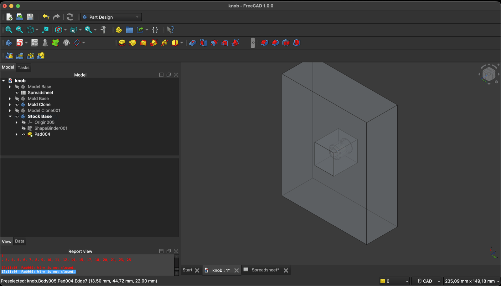
FreeCAD model tree listing Model Base, Spreadsheet, Mold Base, Mold Clone, Model Clone001 and Stock Base containing Origin005, ShapeBinder001 and Pad004, with the stock block and the knob inside it in the 3D view
Tree: Model Base, Spreadsheet, Mold Base, Mold Clone, Model Clone001, Stock Base. The mold block and the knob sit centred inside the stock.

Last step, the same Boolean as before. The operation dropdown defaults to Fuse, which would weld the mold into the stock instead of taking it out.
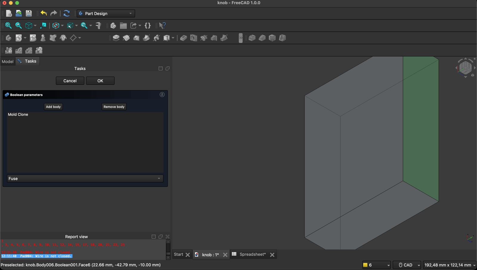
FreeCAD Boolean parameters dialog listing Mold Clone with the operation dropdown set to Fuse, and the stock block in the 3D view with one face shaded green
Boolean with Mold Clone in the list, operation still on Fuse.
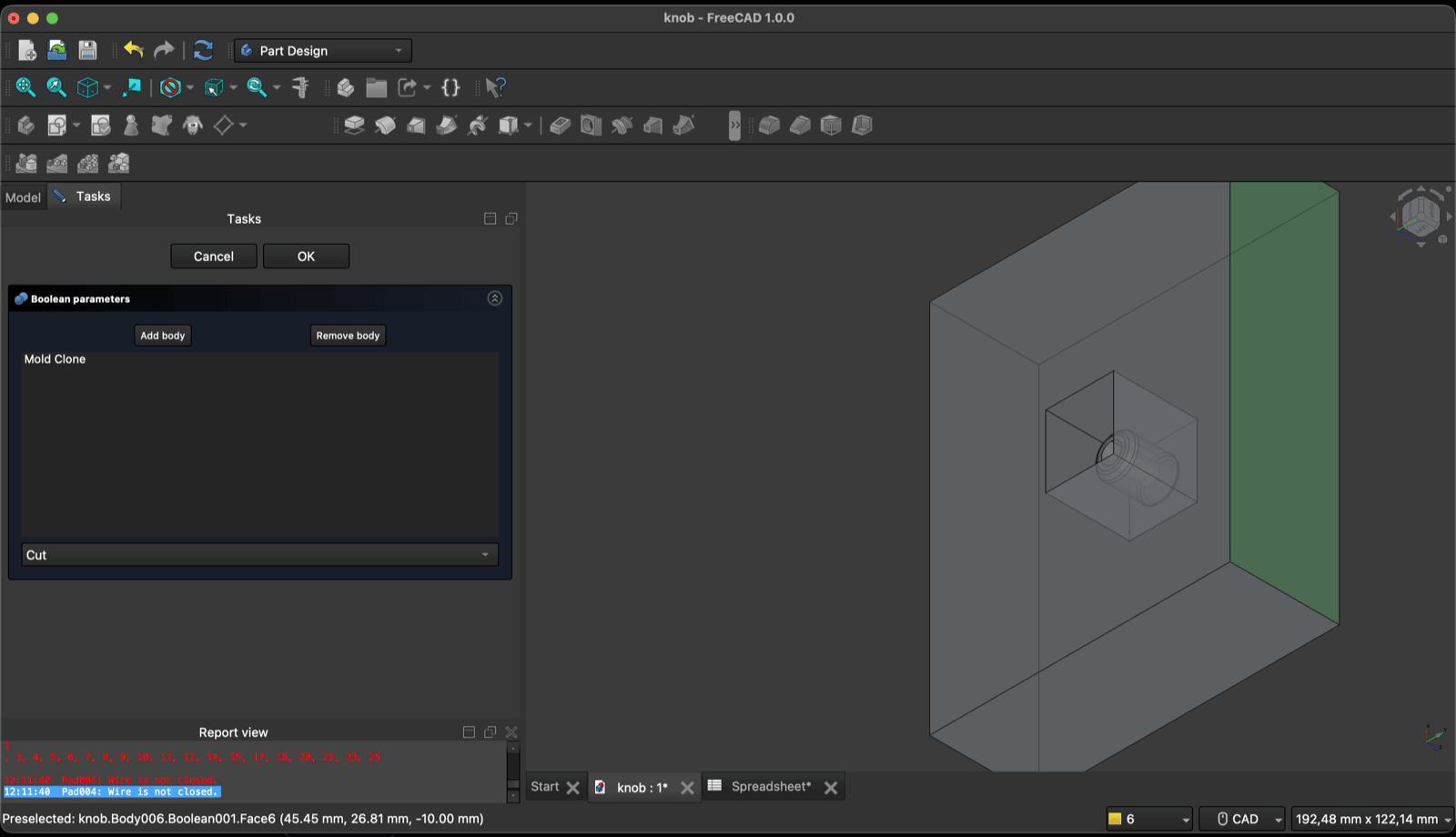
FreeCAD Boolean parameters dialog with the operation set to Cut, the stock block now showing the mold block and the knob as an internal cavity
Switched to Cut. The mold block and the knob now read as a cavity inside the stock.

That is the file the mill gets: a part positioned in a stock of a known size, both driven from the spreadsheet.

5. Milling the Wax Master

The mill is the Fablab's Roland MDX-40, driven from VPanel in NC code mode, with the CAM done in VCarve Pro. I leaned on the Aalto Fablab tutorials on YouTube for the workflow and stopped every few steps to redo the numbers for my own job.

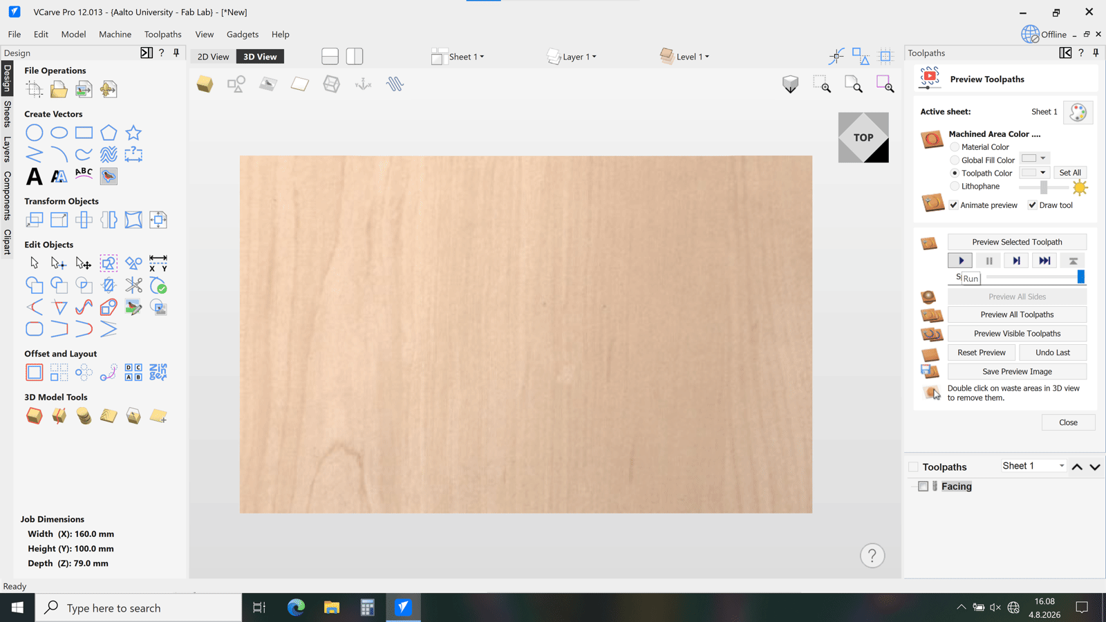
The wax blocks in the lab get reused, so the first session was reclaiming stock: skimming the leftover geometry off the top with a 22 mm end mill until the surface was flat again.
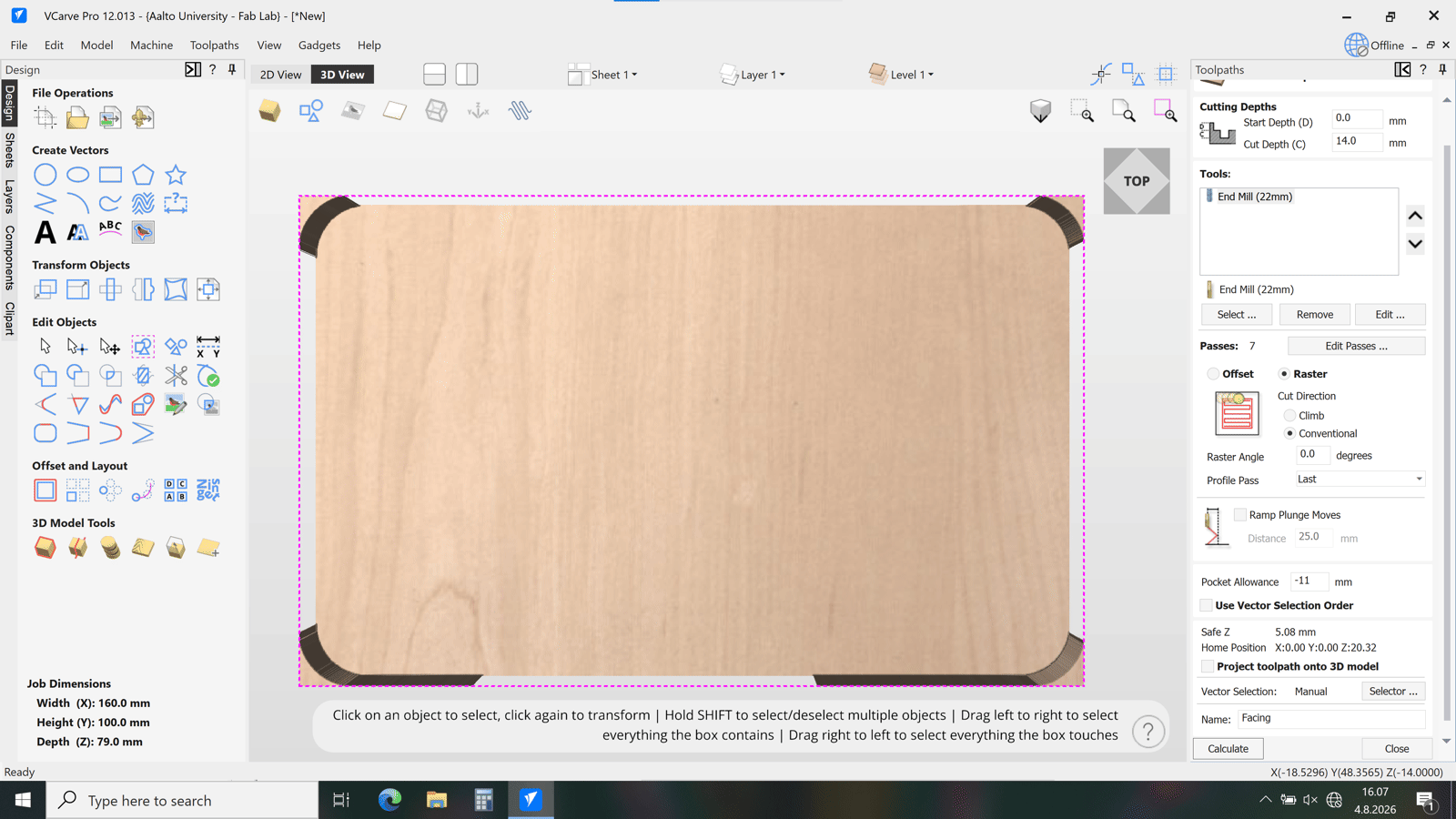
VCarve Pro with a Facing toolpath open, raster strategy, 22 mm end mill, 14 mm cut depth in 7 passes, over a 160 by 100 mm job
Facing toolpath on the first block: 22 mm end mill, raster, 14 mm total depth over 7 passes. The dark corners in the render are the leftovers being skimmed off.
VCarve Pro toolpath preview panel with the Facing toolpath listed and the material rendered clean and flat
Preview of the facing pass. Flat is the whole job.
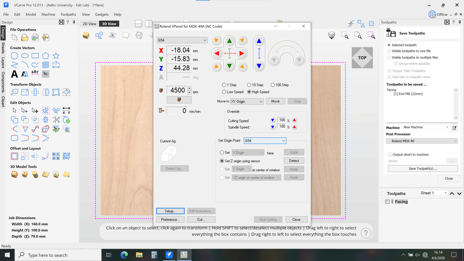
Roland VPanel for MDX-40A over VCarve, spindle at 4500 rpm, Set Z origin using sensor selected, with the Facing toolpath queued for saving through the Roland MDX-40 post processor
VPanel over the save dialog. Z origin comes from the sensor, and the post processor is still set to Roland MDX-40 here, which turned out to be wrong.

Saving that toolpath taught me the post processor lesson of the week. The Roland MDX-40 post writes a .rol file, and the VPanel on the lab machine runs in NC code mode, which does not take it. The combination that works is the USBCNC (mm) post, which writes the .nc the panel expects. Both versions are in the files below because I only found out by trying.
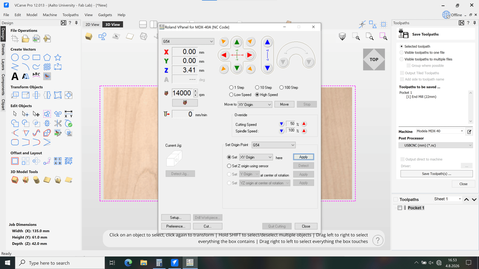
VPanel and VCarve with a Pocket toolpath for a 135 by 61 mm wax block, cutting speed override at 50 percent, post processor set to USBCNC mm
Facing the block I actually used, run as a Pocket toolpath. Post processor now USBCNC (mm), cutting speed override at 50%.

Then the mold itself. The Boolean result from section 4 went out of FreeCAD as an STL and into VCarve through Import 3D Model, sunk 27.52 mm below the top of the material so the cavity sits at the right depth in the block.
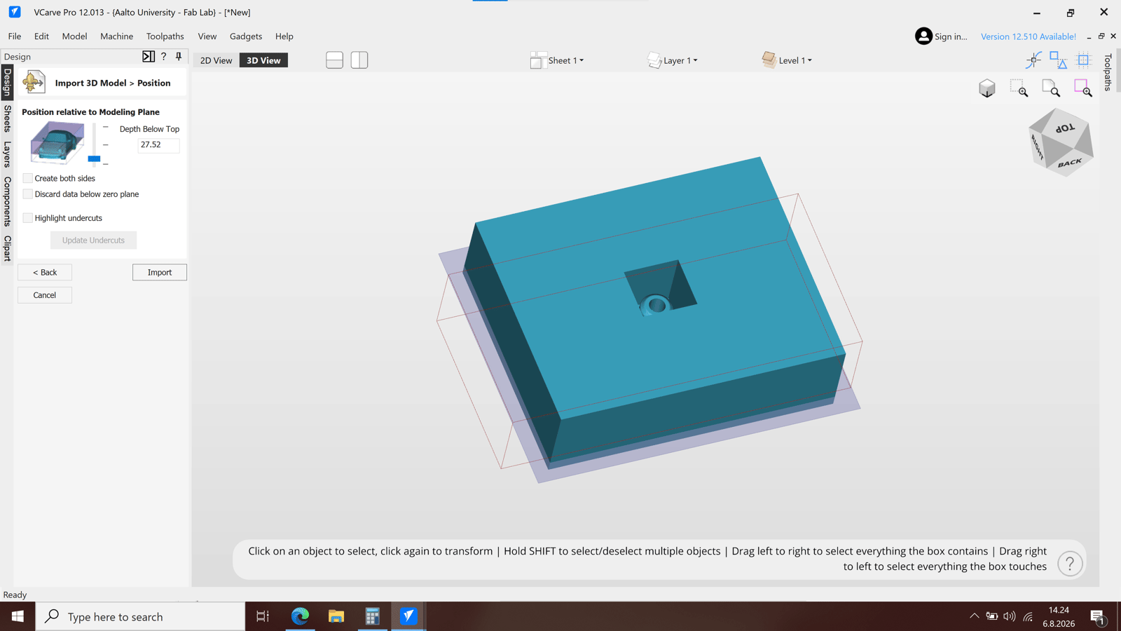
VCarve Import 3D Model dialog with the mold block positioned relative to the modeling plane, Depth Below Top 27.52 mm
Import 3D Model. The block with the knob cavity, positioned 27.52 mm below the top of the stock.

The cutter is a 2 mm ball nose. I set it up in the tool database with the numbers worked out from the tutorials: 14000 rpm, 1120 mm/min feed, 280 mm/min plunge, 0.8 mm pass depth, 0.2 mm stepover. Writing them here so I do not have to derive them again.
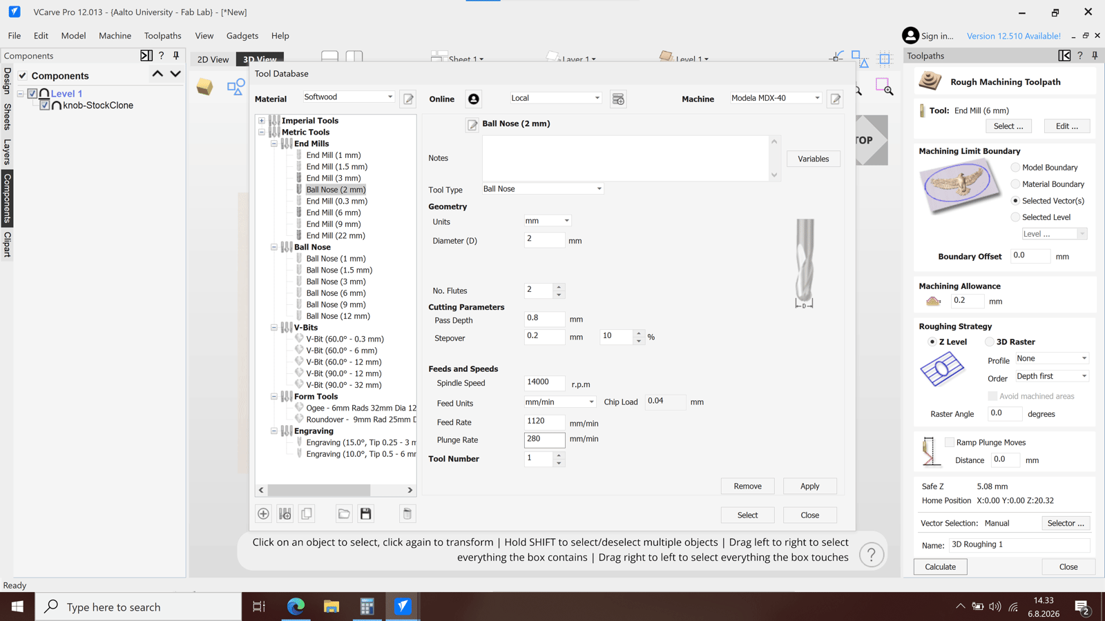
VCarve tool database showing a 2 mm ball nose with 2 flutes, pass depth 0.8 mm, stepover 0.2 mm, spindle 14000 rpm, feed 1120 mm per minute, plunge 280 mm per minute
The 2 mm ball nose in the tool database with the wax settings dialled in.

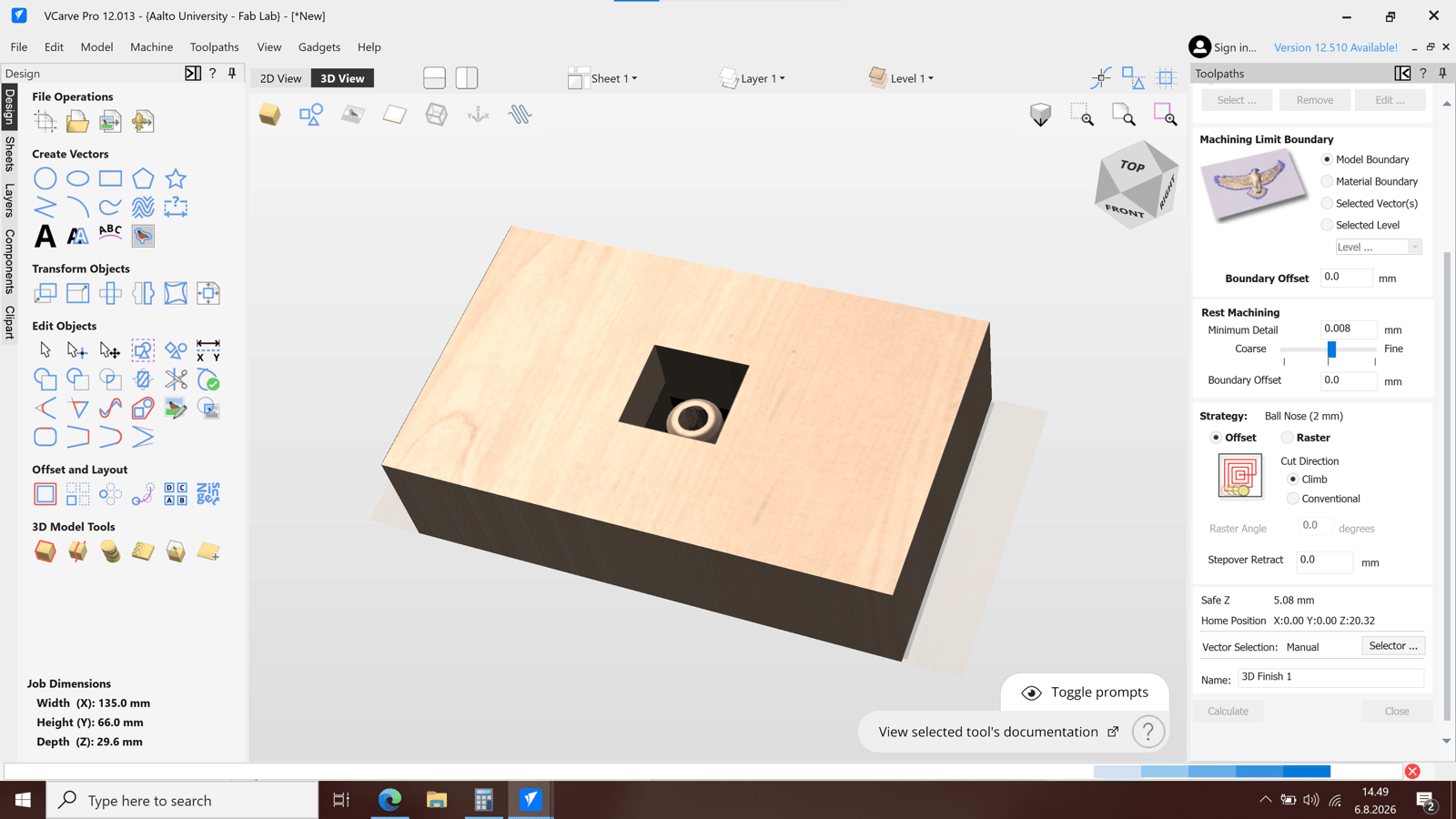
Two toolpaths over the model: a Z-level roughing pass leaving a 0.2 mm skin, then an offset finishing pass to take the skin off. The knob is small and there is not much wax around the cavity, so the walls of the future silicone mold are thinner than I would like. I saw that in the preview and went with it anyway. Redoing the model at that point was a worse deal than living with thin walls on a first iteration.
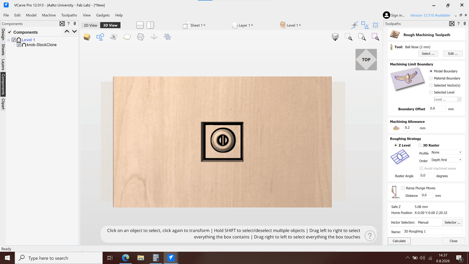
VCarve Rough Machining Toolpath panel with the 2 mm ball nose, model boundary, 0.2 mm machining allowance, Z level strategy, depth first
Roughing: Z level, depth first, 0.2 mm allowance, model boundary.
VCarve Finish Machining Toolpath panel with offset strategy, climb cut direction and rest machining minimum detail 0.008 mm, over a 3D view of the mold cavity
Finishing: offset strategy, climb, with rest machining enabled.
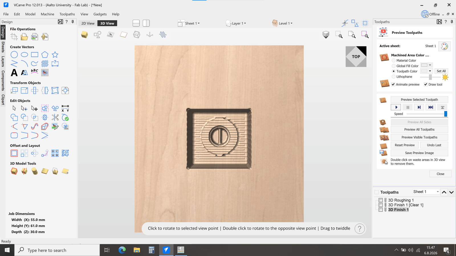
VCarve toolpath preview of the milled cavity with the knob standing in the middle, roughing and two finish passes listed in the toolpath tree
Preview with roughing and the finish passes stacked in the list. The knob stands as a positive inside the pocket.

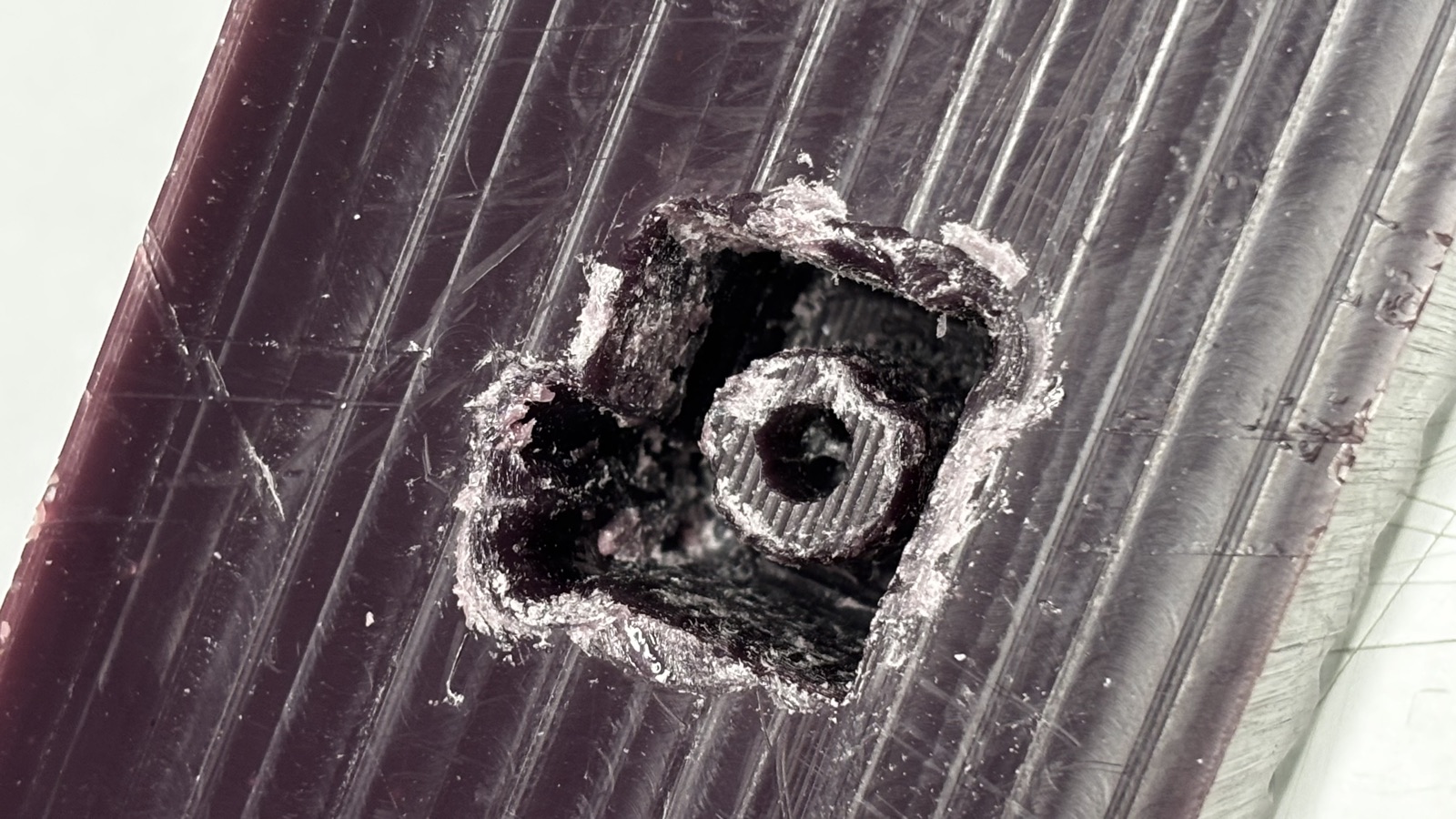
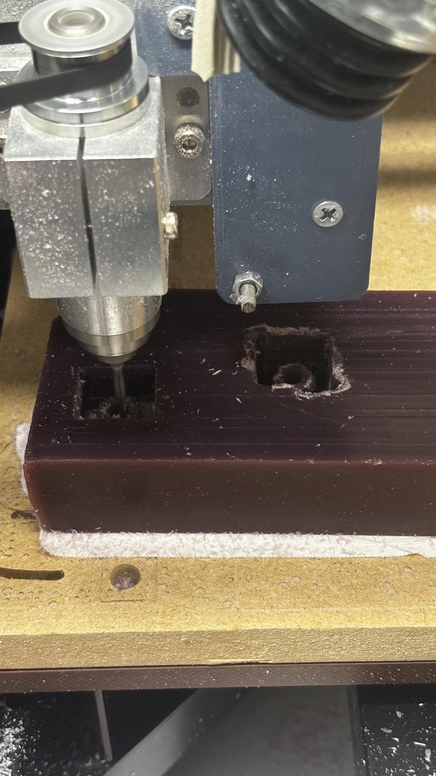
The first attempt went wrong in a way the preview cannot show. The spindle was turning too fast for wax, so instead of clearing as chips the material heated up, smeared and welded itself back onto the walls. The rim of the pocket tore instead of cutting.
First attempt roughing. The pile around the cutter is wax dust that should be leaving, not staying.
Quick look at the first cavity out of the machine.
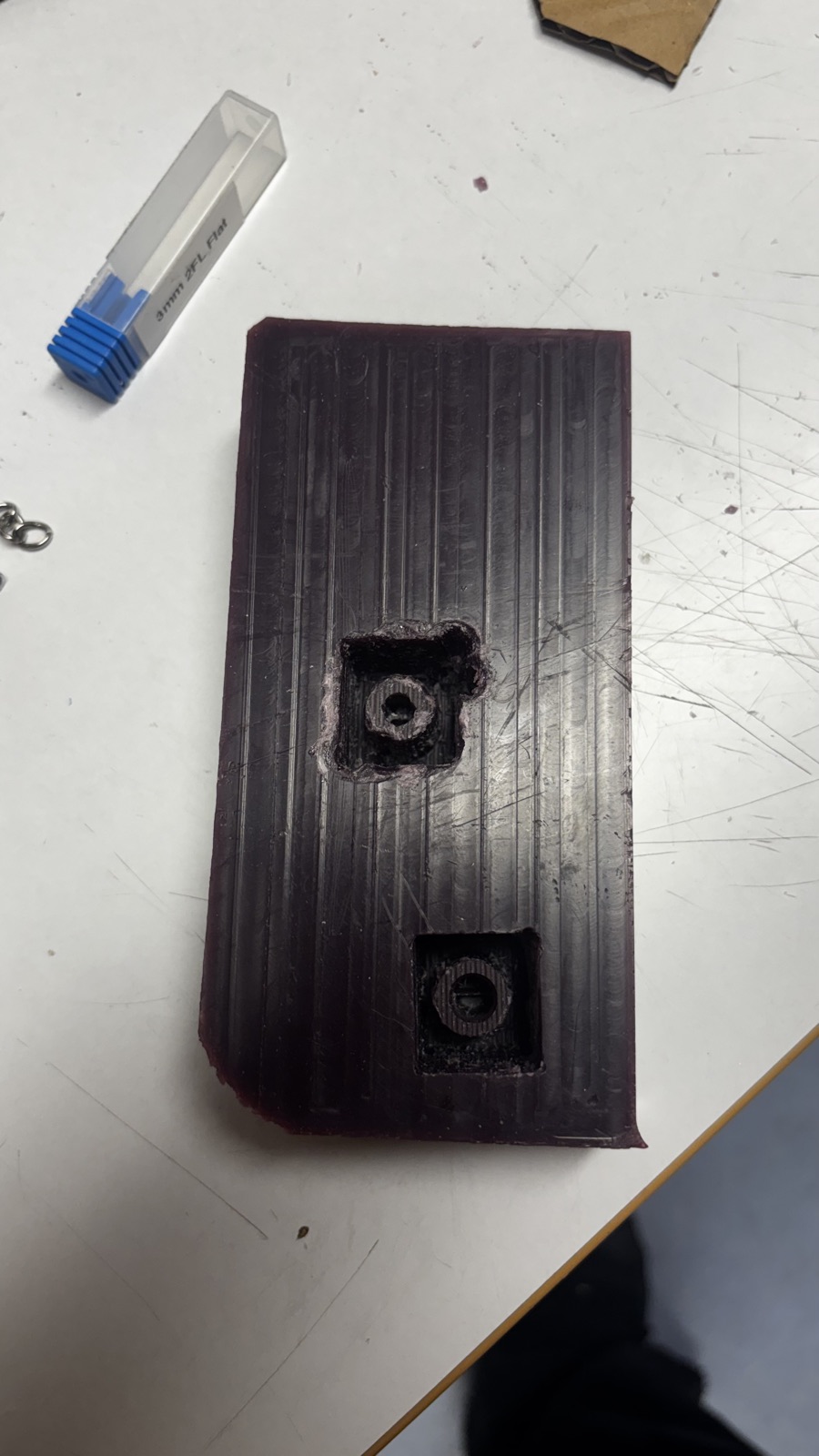
Close-up of the first milled cavity in purple wax with a torn, re-welded rim and melted chips stuck around the knob shape
The first cavity up close. The knob shape is there, but the rim is torn and the melted chips are welded back on.

For the second attempt I dropped the spindle override in VPanel to 20 to 30 percent for the wax. Even 30 percent felt harsh once the cutter was working at the bottom of the pocket. The other change was babysitting the job: instead of letting it run and melt, I kept quitting the cut, cleaning the packed wax out of the cavity, and restarting. The same shape took far longer the second time, but the edges stayed edges.
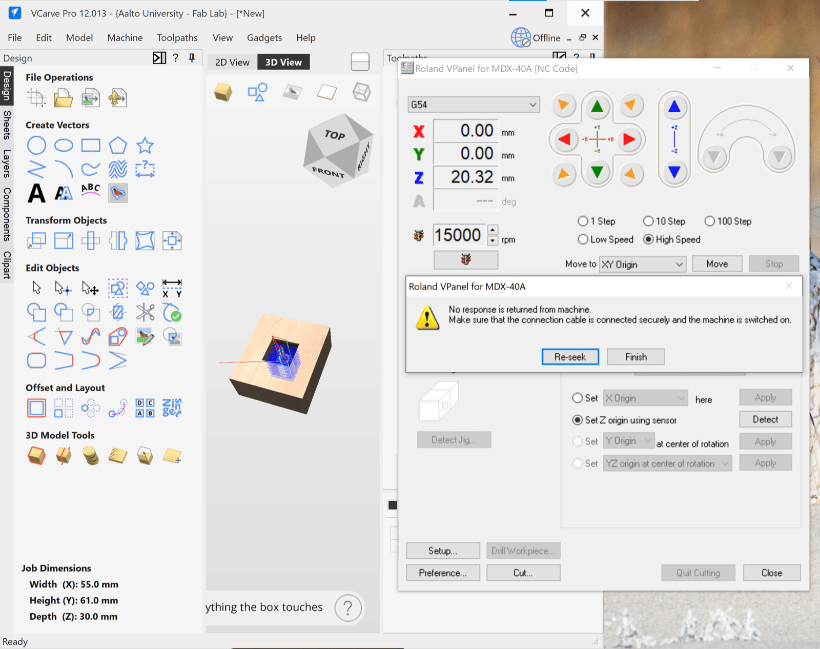
Roland VPanel error dialog reading No response is returned from machine, make sure that the connection cable is connected securely and the machine is switched on
The price of all the stopping and restarting: VPanel losing the machine between runs.
The 2 mm ball nose cutting the second cavity in the wax block, with the rough first cavity visible beside it
Second cavity under the cutter, first attempt sitting next to it for comparison.
Second attempt running slow. Chips instead of melt.
The wax block on a table with both milled cavities, the first one rough around the rim and the second one clean
Both cavities out of the machine. First attempt at the top, second attempt below it.

The first cavity is scrap. The second one is a bit rough around the edges but the knob, its bore and the fillets all read clearly in the wax. For a first iteration of modelling, milling and casting on my own, I am counting it as a win.

6. Pouring the Silicone Mold

The wax block is the positive. Silicone poured over it becomes the flexible negative that the actual knobs get cast in later. In the casting room I looked for a kit that was already open before breaking the seal on a new one, and found SORTA-Clear 37, a platinum silicone that happens to be food safe. Less than half of it was left and the material had gone noticeably stiff in the bottle. I am not sure how much that matters, but it did still mix.
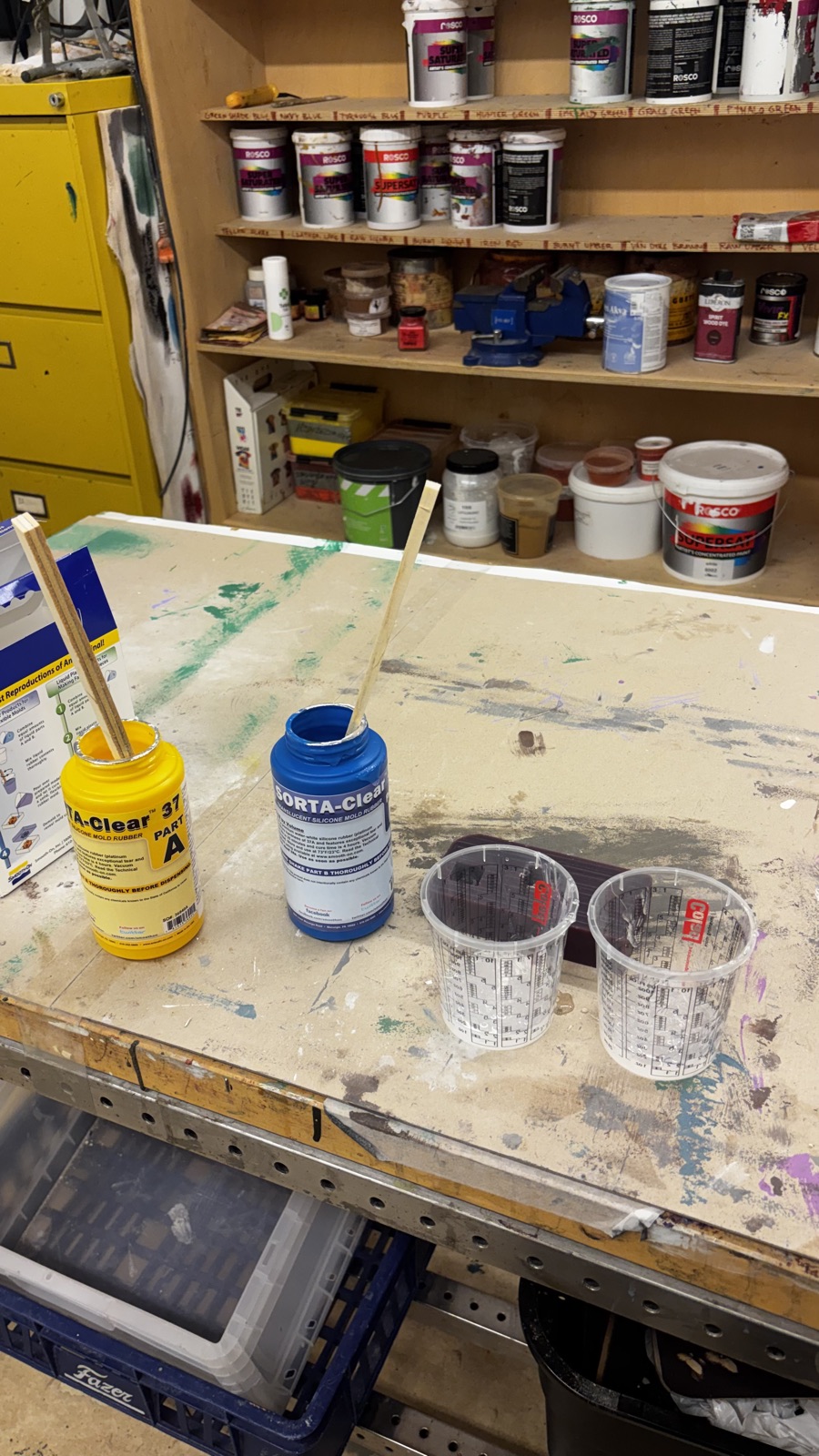
SORTA-Clear 37 part A and part B bottles with stir sticks on a casting room workbench, two empty measuring cups beside them and the wax mold behind
SORTA-Clear 37, parts A and B, with the wax block waiting behind the cups.

The ratio is 1:1 by volume. I measured the parts into separate cups, combined them and stirred. I misjudged how much the cavity needed and mixed roughly double, which is the note to self for next time.
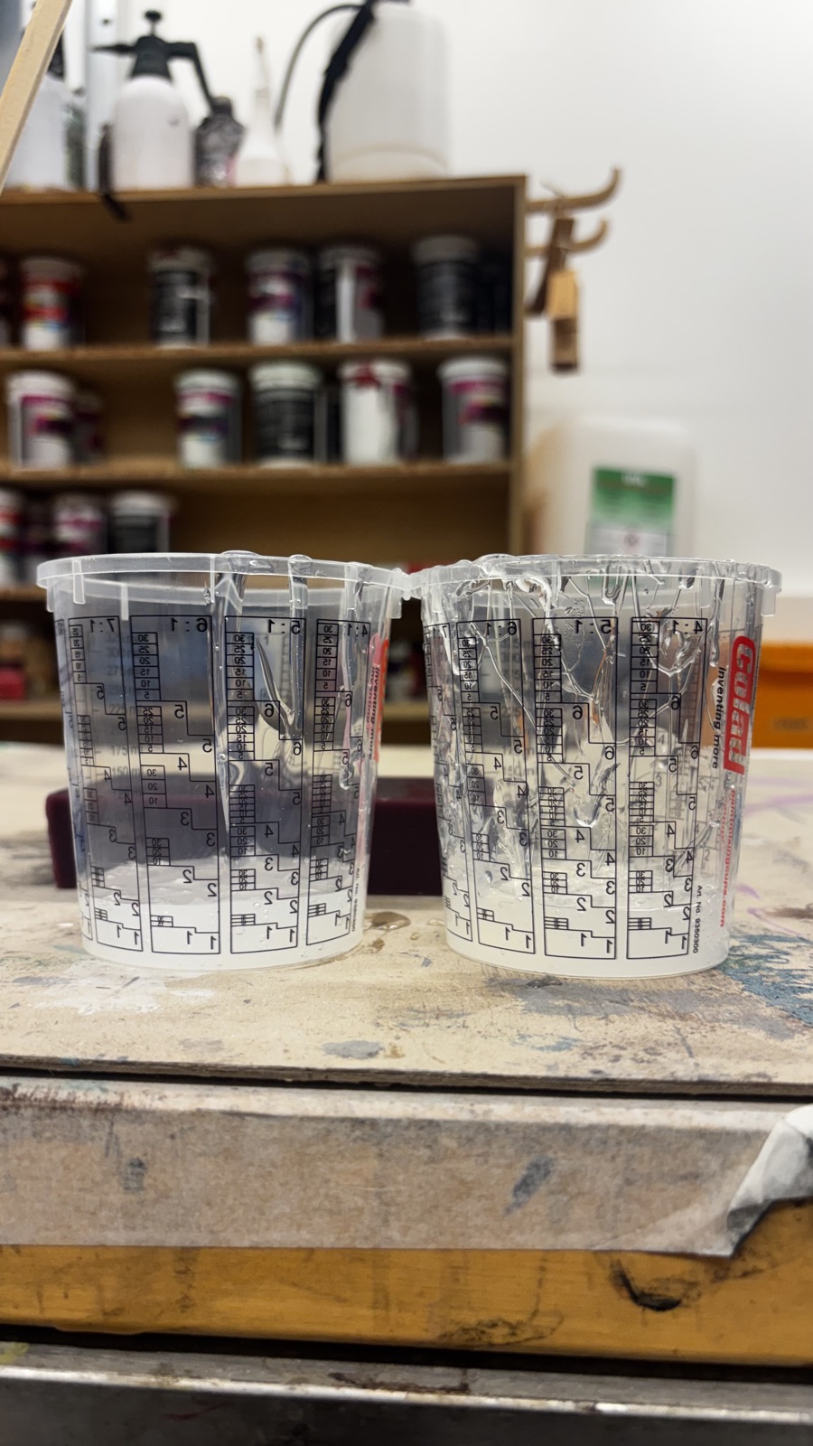
Two graduated mixing cups side by side with equal amounts of clear silicone in each
Parts A and B measured out.
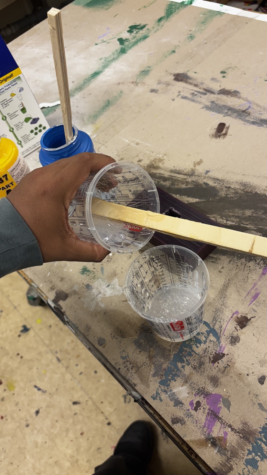
One measuring cup being emptied into the other over the workbench, with the wax mold lying next to them
Combining the two parts into one cup.
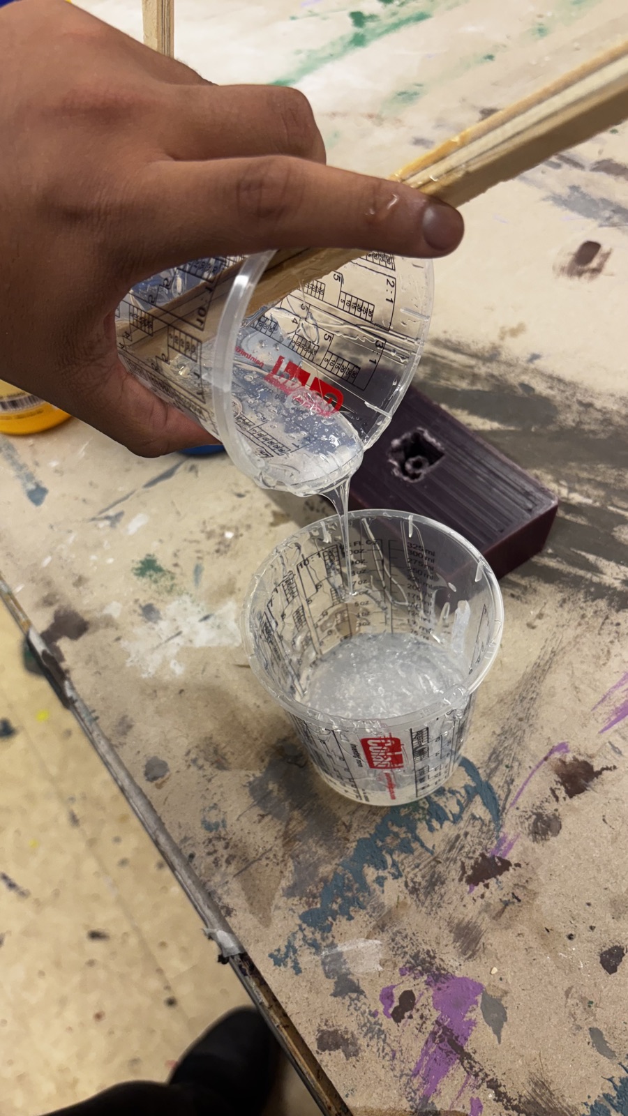
Thick clear silicone stretching in a slow string from one cup into the other
How the old material pours. It stretches more than it flows.
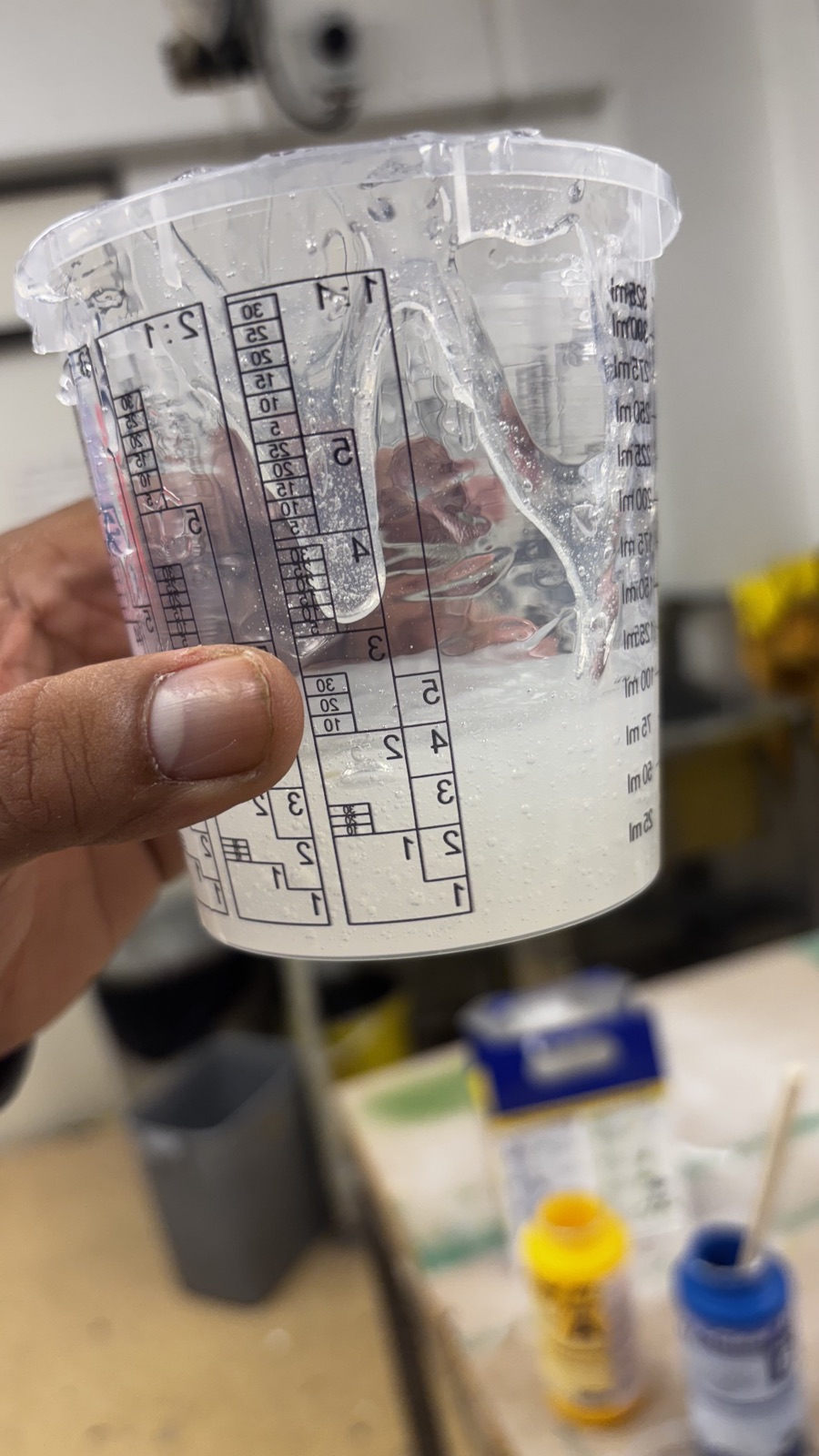
A hand holding the mixing cup with the combined silicone, milky and full of small air bubbles
Mixed and full of air, which is what the vacuum chamber is for.

The cup went into the vacuum chamber to degas before pouring.
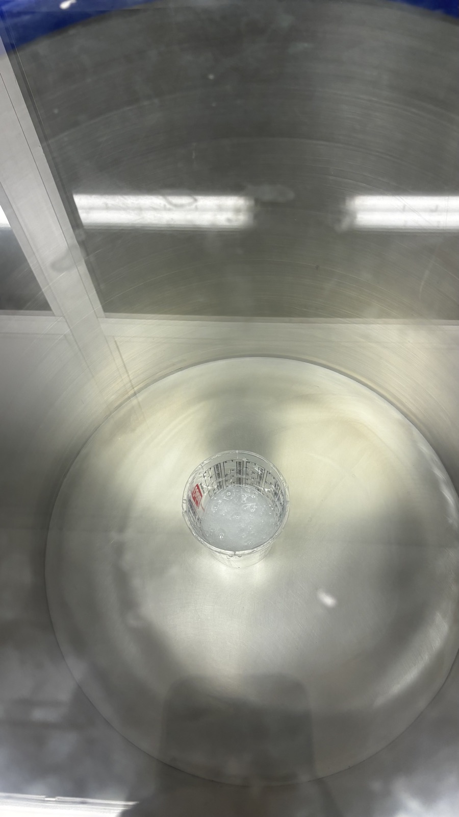
The mixing cup with silicone sitting on the plate inside the vacuum chamber, seen through the glass lid
The cup on the chamber plate, through the lid.
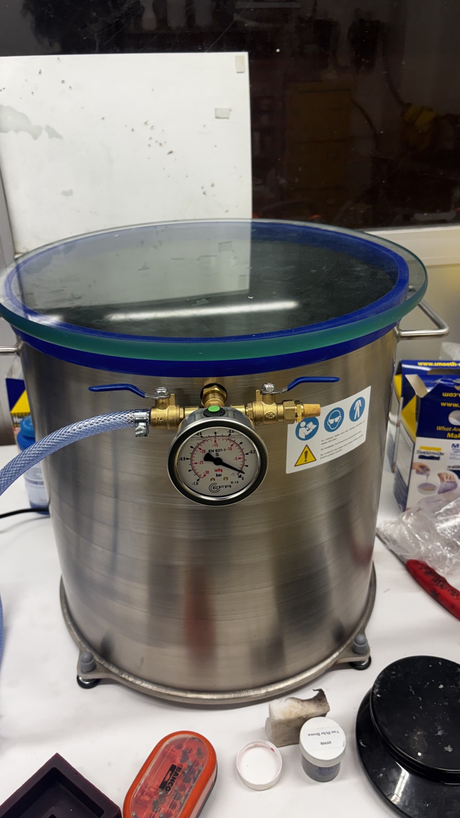
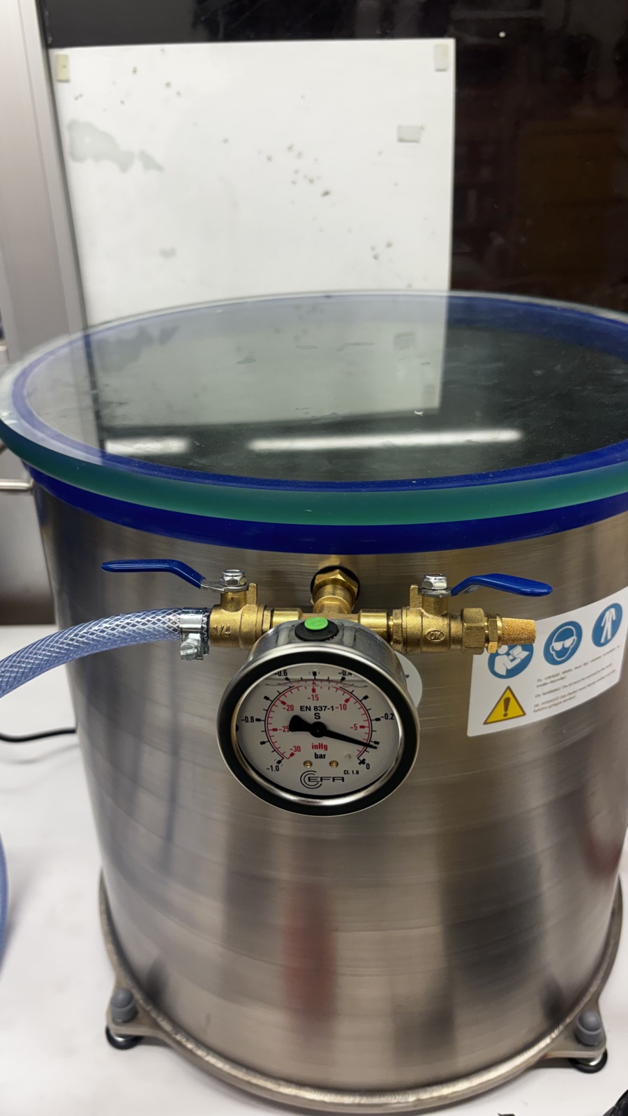
The stainless steel vacuum chamber with glass lid, brass valves and gauge on the casting room bench, hose attached
The chamber closed up with the pump hose on.
Close view of the vacuum gauge on the chamber pulling down toward negative one bar
The gauge pulling down toward a full bar of vacuum.
Degassing. The bubbles rise, swell and pop under vacuum.

After twenty minutes there were still bubbles coming up, probably helped by how stiff the material was to begin with. I had to leave, so it got poured as it was.

Pouring into the wax mold.

Demolding happens tomorrow. If the bubbles ruined it, the redo is Mold Star 30: the mold itself has no reason to be food safe, and a second pass through the same process with fresh material and a proper degas should come out better. The knobs themselves come after that, and picking their resin is still open.

7. Demolding and Trimming

Next day. The silicone had set overnight, firm under a finger, so the bubbles did not ruin it and the Mold Star redo stays on the shelf.

Checking the cure before committing to pulling anything out.

Both cavities released without a fight. Silicone flexes and wax does not grab, so each mold came out whole, wearing a thin skirt of flash where the overpour had spread across the top of the block.
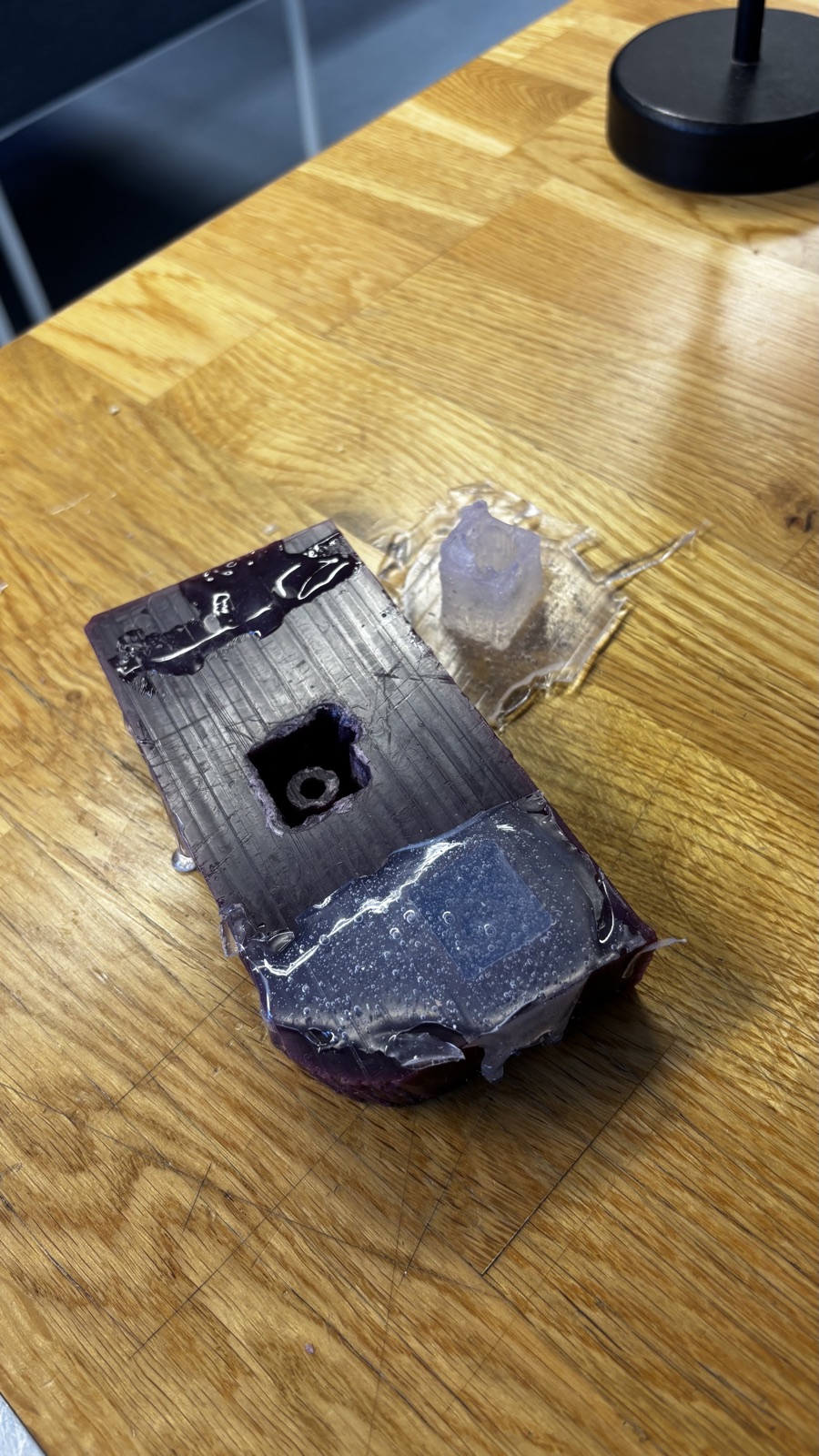
The purple wax block with one cavity already empty and the second silicone piece still in place under its glossy flash, the first demolded mold lying on the table behind it
First mold out, the second still sitting in its cavity.
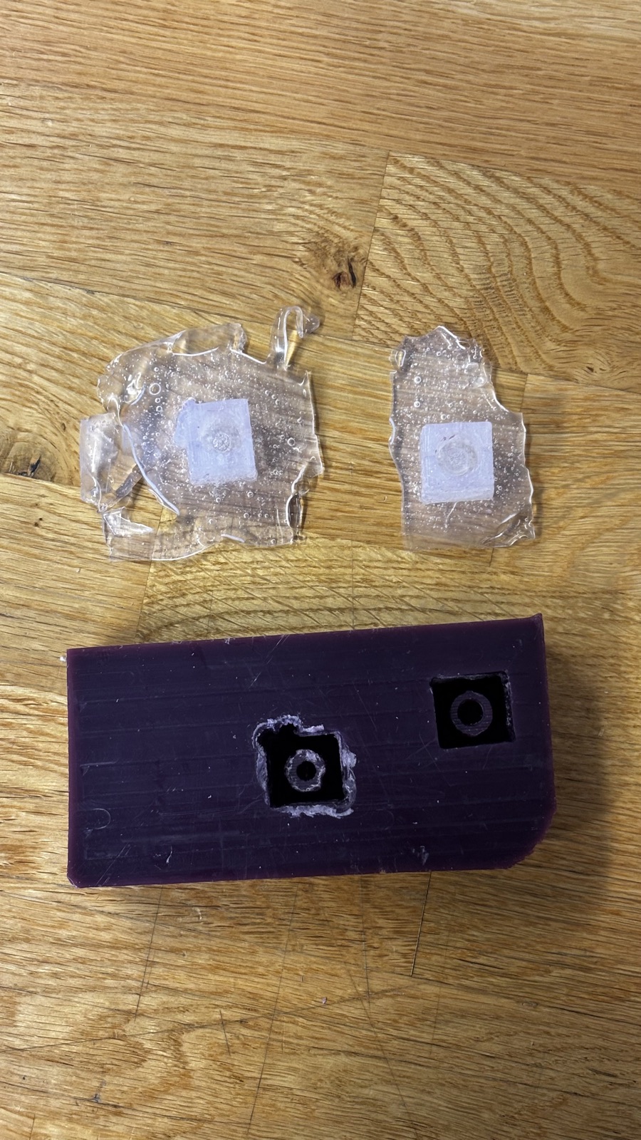
The emptied wax block with both cavities open, and the two demolded silicone pieces with their flash skirts lying above it
The wax block emptied, both silicone pieces beside it. The wax survives for the next person to face off and reuse.

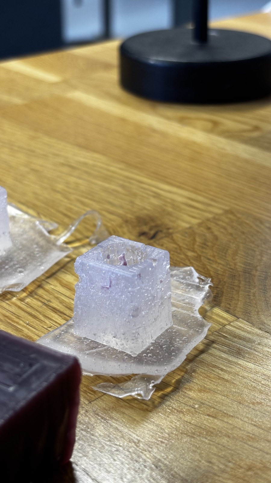
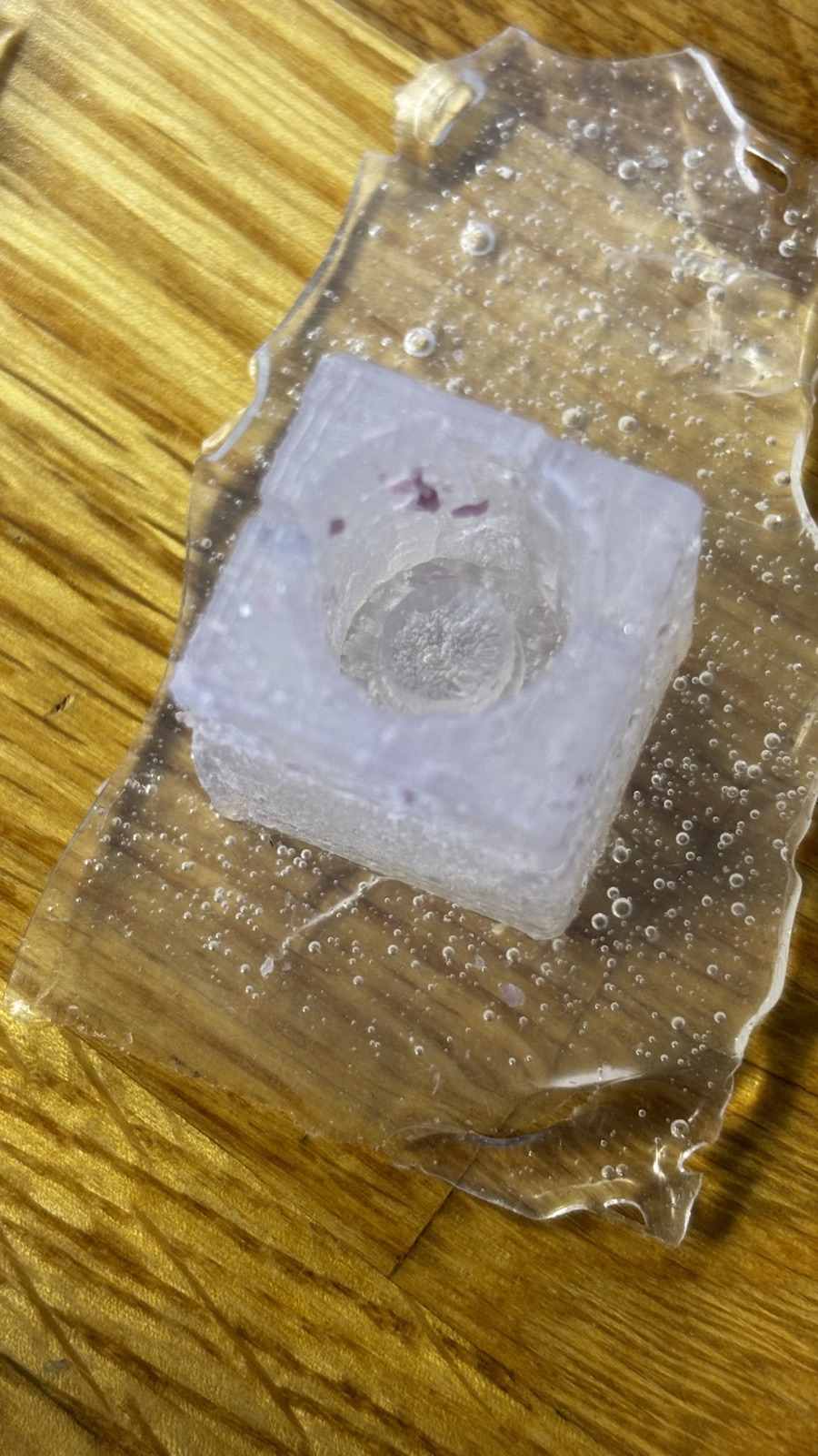
The detail transfer is the part that sold me on the process. The tool marks from the milling read on the silicone walls, and a few crumbs of purple wax came along embedded in the surface. The air I never got out in the degas shows as pinprick bubbles in the flash and speckled through the body of each block, but the cavity surfaces came out clean enough to cast in.
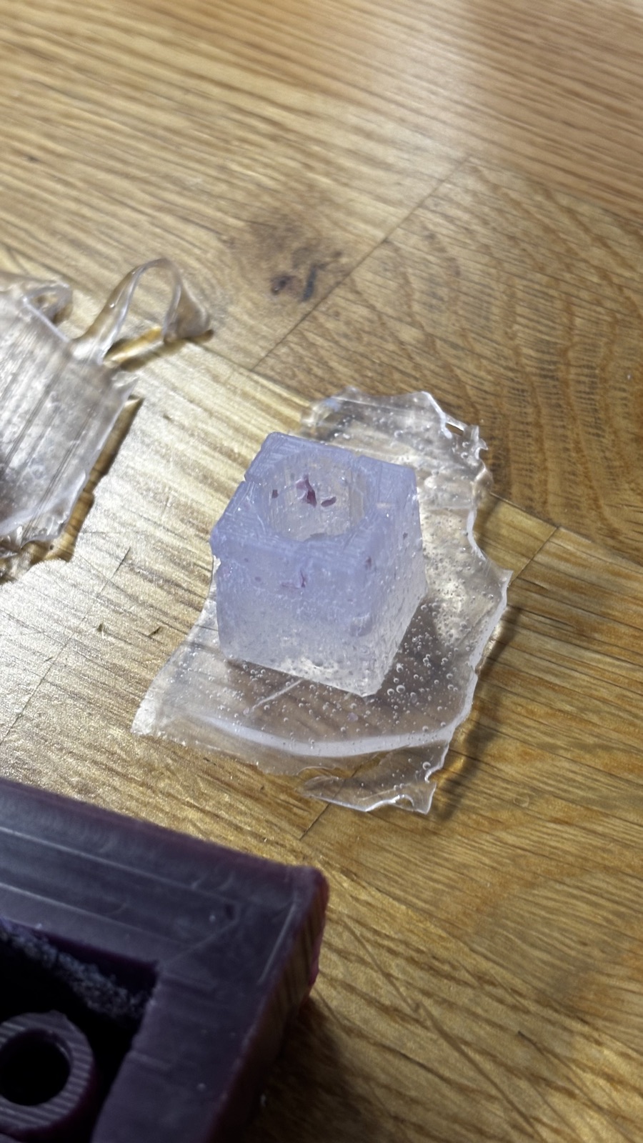
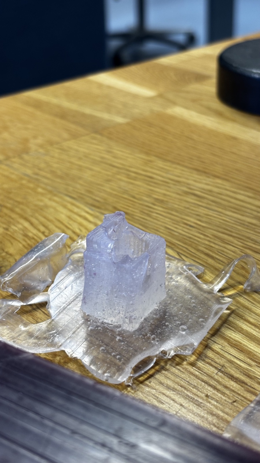
Close view of a demolded silicone mold cube with the knob cavity on top, sitting on its sheet of clear flash, flecks of purple wax embedded in the surface
One mold still on its flash. The purple flecks are wax that came along for the ride.
Side view of a silicone mold cube standing on its wrinkled flash skirt, fine horizontal ridges from the milling visible on its walls
Side on. The horizontal ridges are the milling passes, carried over from the walls of the wax pocket.
The second silicone mold cube on its flash sheet next to the edge of the wax block, the round knob cavity visible on top with small bubbles in the surrounding sheet
The second mold, bubbles through the flash sheet and the body of the block.
Top down view into the knob cavity of a silicone mold, a round opening with a central post standing in the middle
Looking into the cavity. The post in the middle is the encoder bore, now a positive.

Then the trim: the flash cut away until both blocks stood flat on their own.
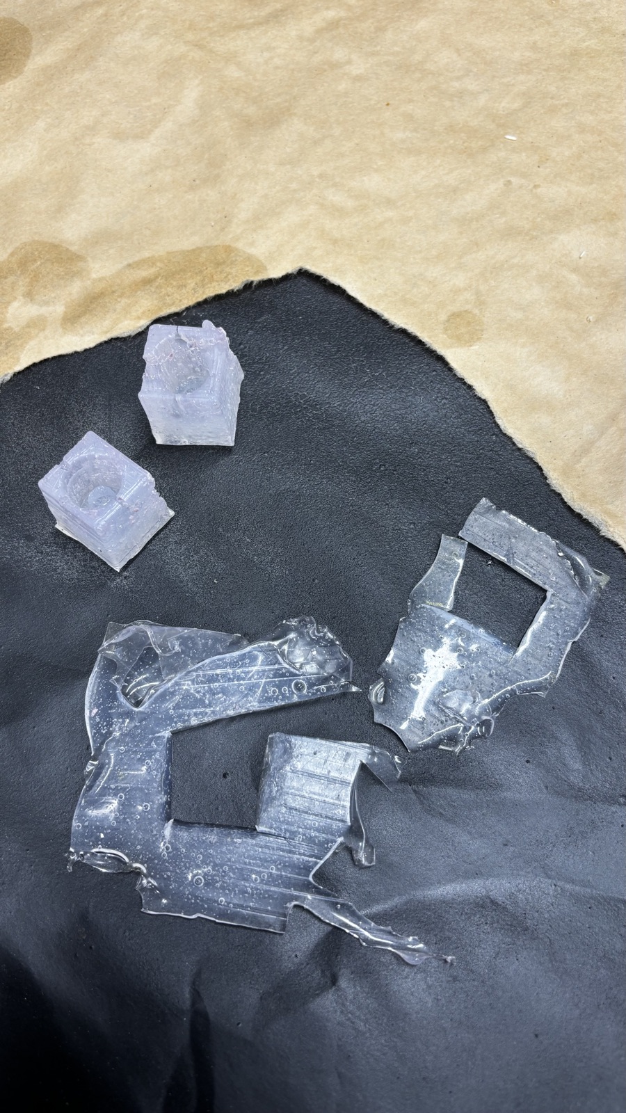
Both trimmed silicone mold cubes on a black mat with the cut away pieces of clear flash lying next to them
Both molds trimmed, with everything that came off them.

8. Casting with Smooth-Cast 305

For the knobs themselves the casting room had Smooth-Cast 305, a liquid plastic that cures white: 1A:1B by volume, seven minutes of pot life, thirty minutes to demold. That is the plastic fallback from section 1, so these knobs come out hard rather than rubberized.
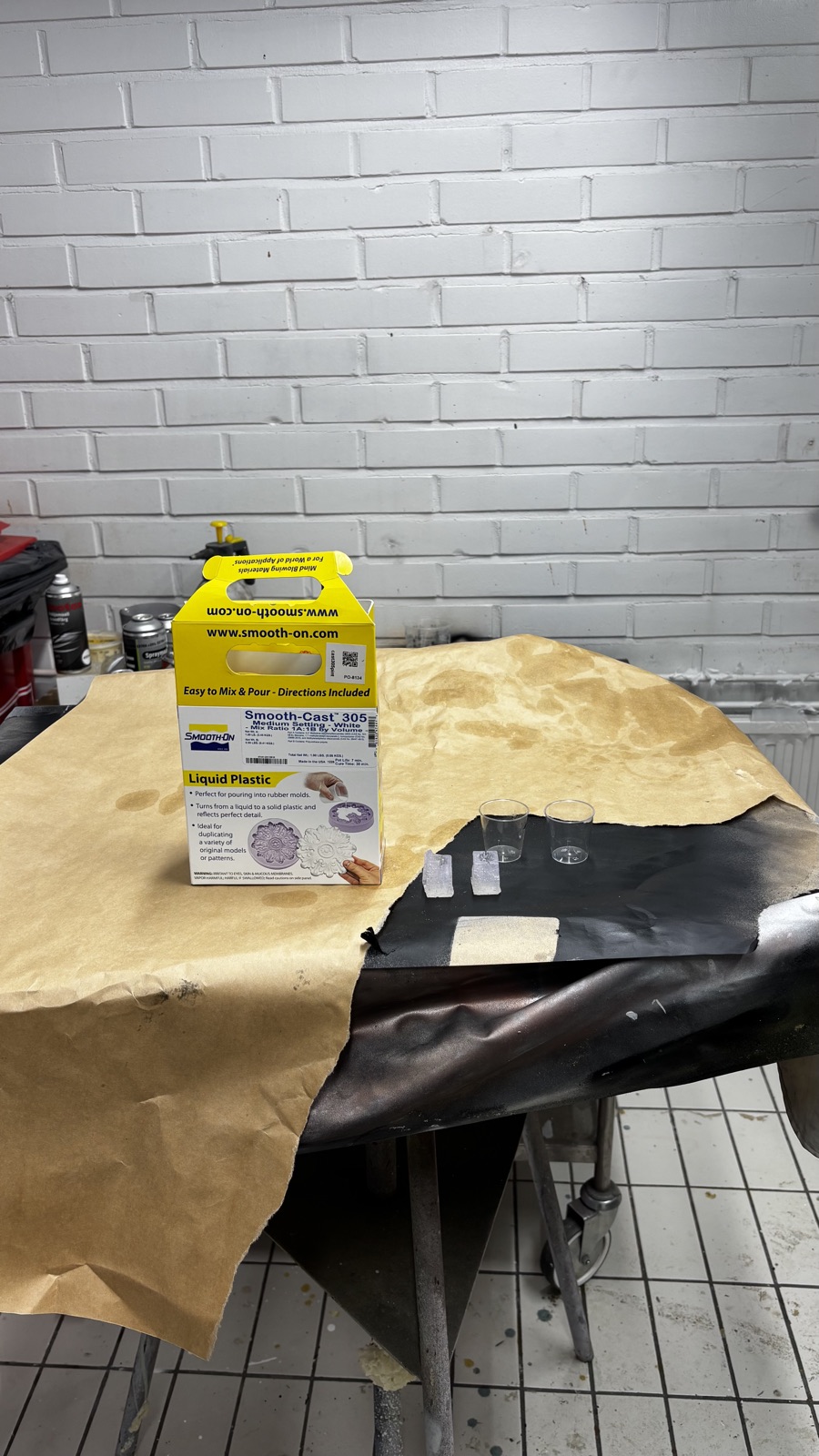
The yellow Smooth-Cast 305 box on the casting room bench with two small mixing cups and the two trimmed silicone molds lined up next to it
Smooth-Cast 305 with the cups and both molds staged.
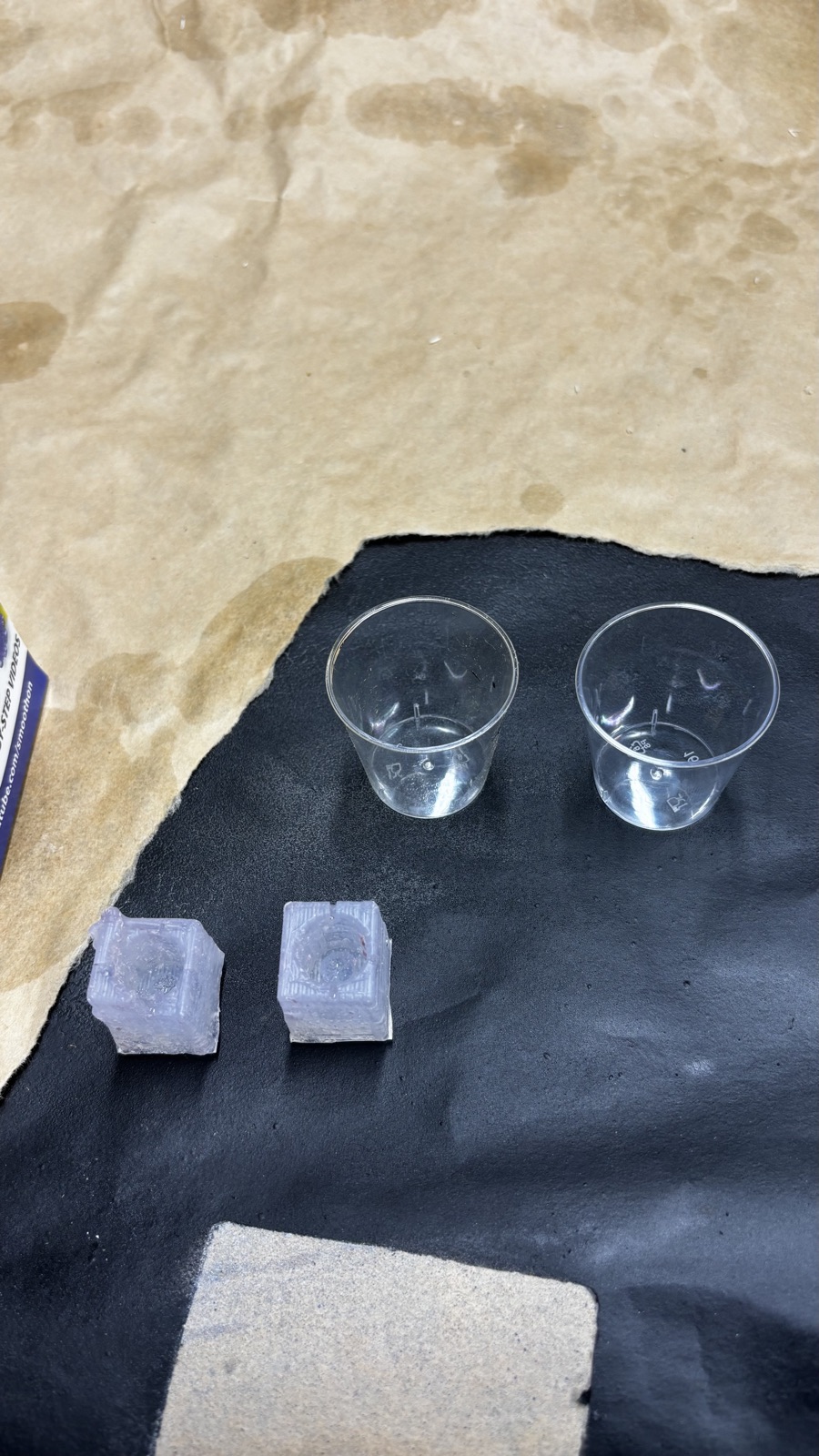
Two empty plastic mixing cups on the black mat with the two trimmed silicone molds below them
Cups and molds before measuring.

The kit fought back before it opened. The part A container was glued shut where the material had hardened around the lid on its own, and it took a pair of scissors to cut through the crust and crack it open.

Equal volumes into two cups, then both into one and stirred.
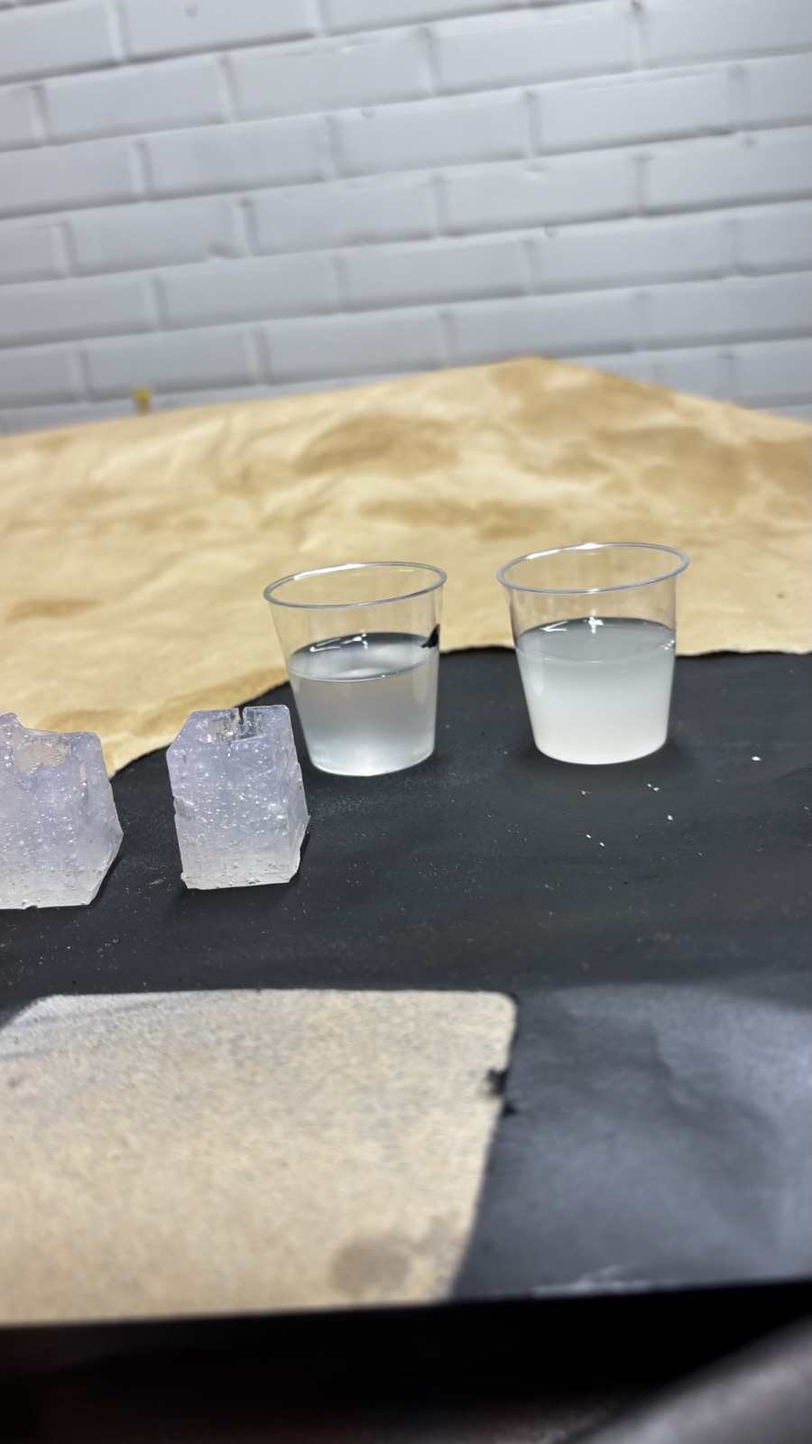
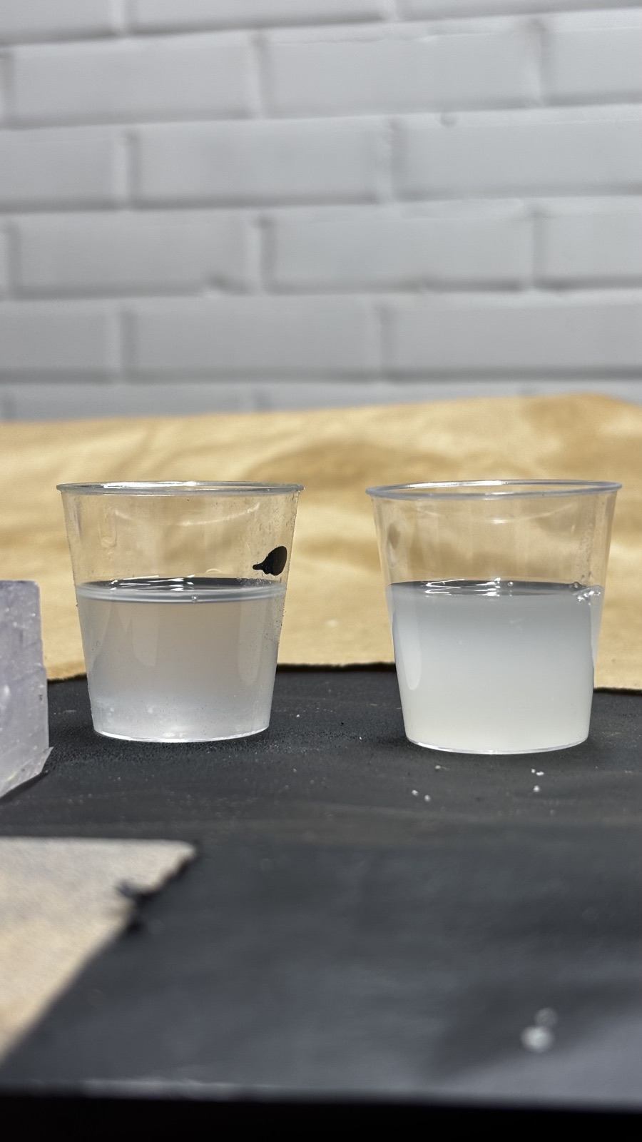
Two small plastic cups with equal amounts of resin, one nearly clear and one milky white, the trimmed molds standing to the left
Parts A and B measured out.
Close view of the two cups side by side, the left resin water clear with a slight tint, the right one opaque milky white
One part pours clear, the other milky. Together they cure white.
A graduated mixing cup with ratio markings holding the combined white resin and a wooden stir stick, the two emptied small cups beside it
Combined and stirred, with the pot life clock running.

The pour went into the mold that came from the better of the two cavities.
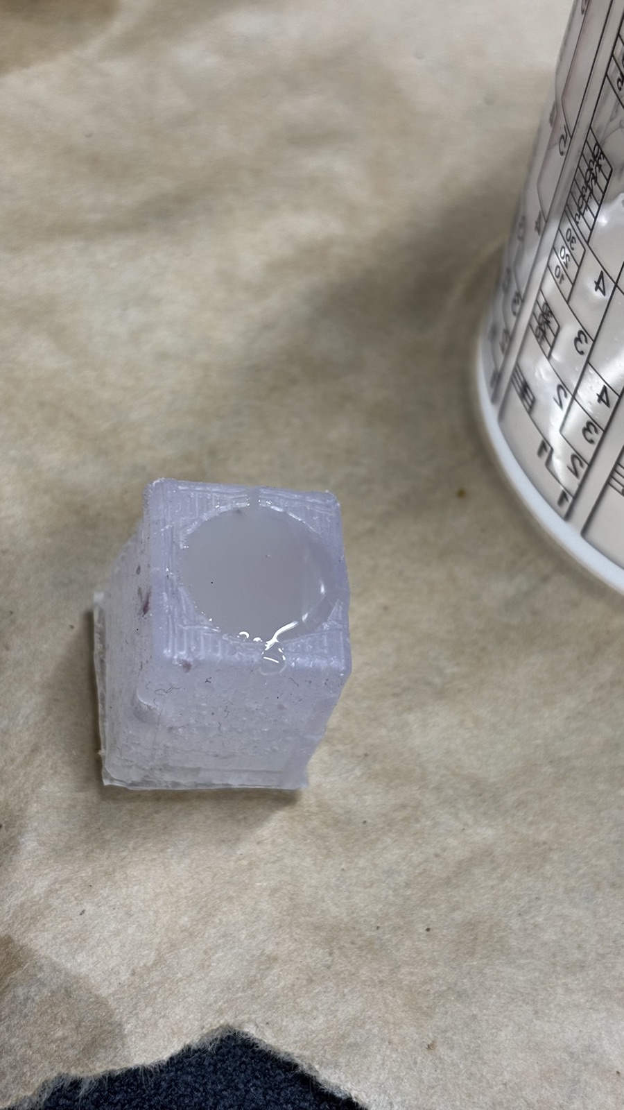
The trimmed silicone knob mold with its round cavity filled with white resin, a graduated mixing cup lying behind it
The better knob's mold filled.

There was resin left over, and with seven minutes of pot life it was use it or bin it. Other molds from other people's projects were lying around the room, and some of the shapes looked interesting, so the leftover got shared out across those instead of the bin.
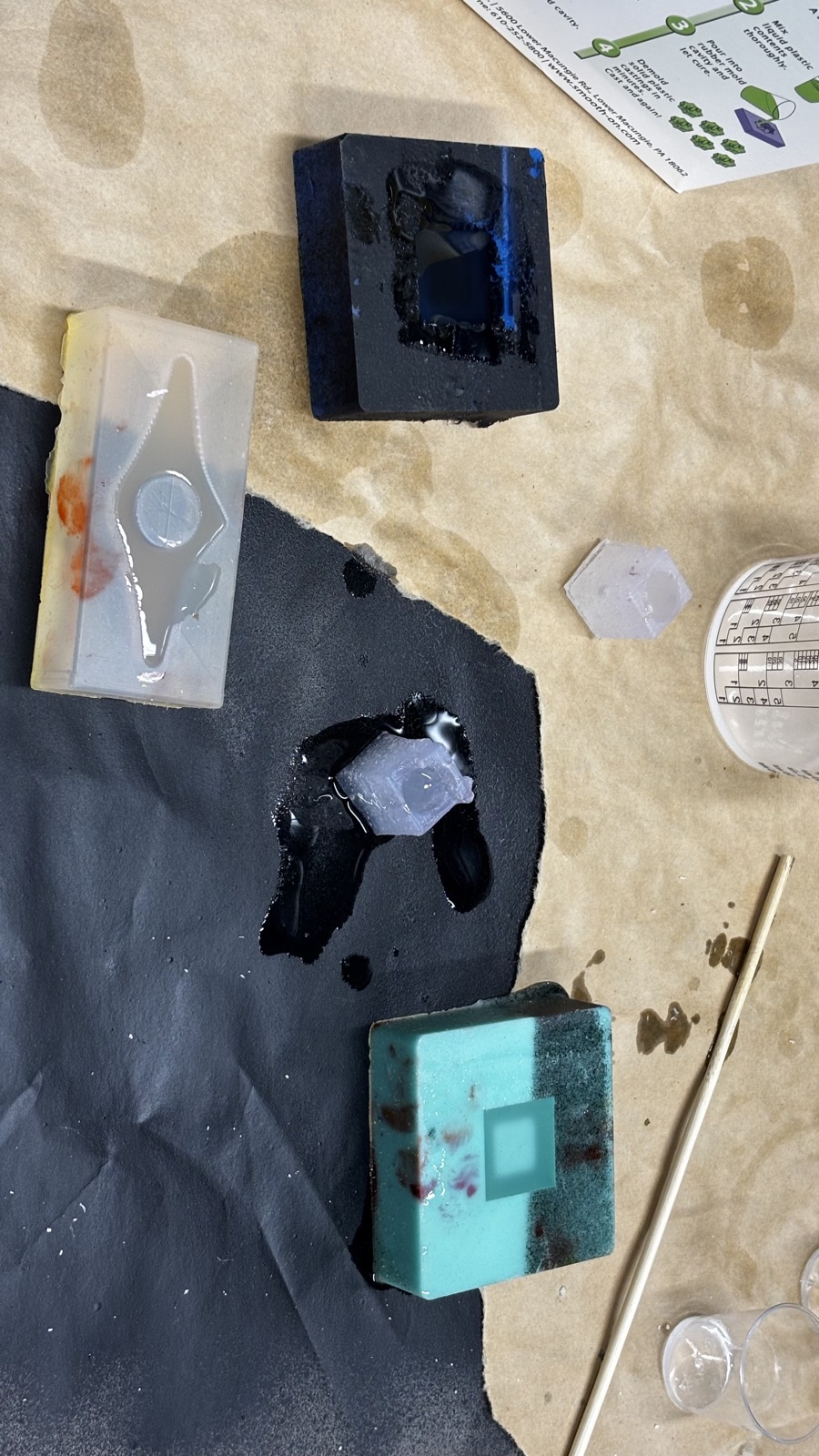
Found silicone molds on the bench holding leftover resin, a white mold with a pointed cavity, a dark mold, a teal mold with a square cavity, a small hexagonal piece and a mold cube sitting in a pool of spilled resin
The leftover shared out across the molds that were around, spill included.

Thirty minutes later the pour had gone from liquid to solid white, in the knob mold and in every found mold that got a share of the leftover.
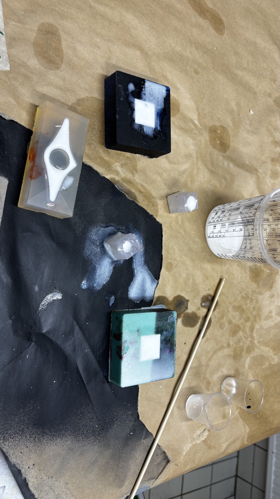
The bench after the cure, a dark blue block and a teal block each holding a white square of resin, a clear mold with a pointed white shape, two small silicone pieces with white resin and the emptied mixing cups on the brown paper
The bench after the cure. Every cavity that got leftover resin holds white plastic now.

The knob pulled straight out of the silicone. The milling ridges from the wax made it through the silicone and into the plastic walls. The open face cured rough where the remaining bubbles collected, since that side of the pour sat against air instead of silicone. Whether the bore underneath seats on the encoder shaft is the next thing to test.
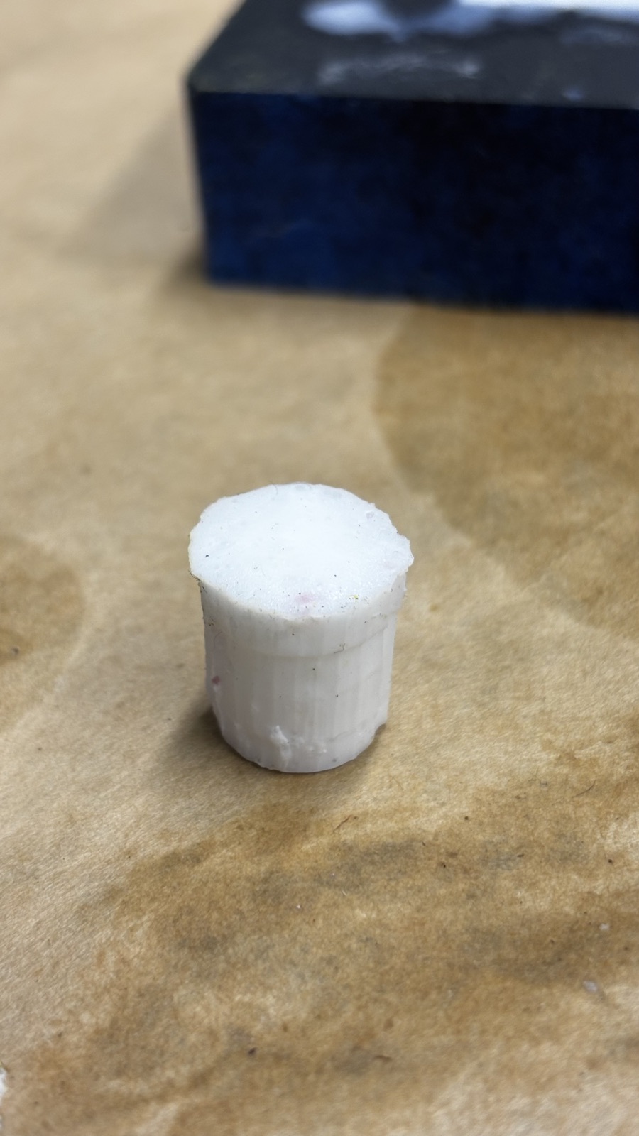
The demolded white knob standing on the brown paper, fine vertical ridges on its side and a rough bubbled top face, the dark blue mold block blurred behind it
The cast knob out of the mold. Milling ridges on the walls, bubbles on the face that cured open to air.

9. Files

Download Knob.crv, the VCarve job for the mold with the roughing and finishing toolpaths.

Download FacingOperation.crv, Facing.rol and Facing.nc, the first facing job. The .rol is the export that VPanel's NC mode refused, kept as a reminder.

Download FacingWaxOperation.crv and FacingWax.nc, the facing job for the block the mold went into.

Download 3D Roughing 1.nc and 3D Finish 1.nc, the exported roughing and finishing passes for the mold cavity.