1. How I Will Use CNC Machining
I needed a small table for my bedroom, somewhere to put a lamp and a book. I used this assignment to actually make it.
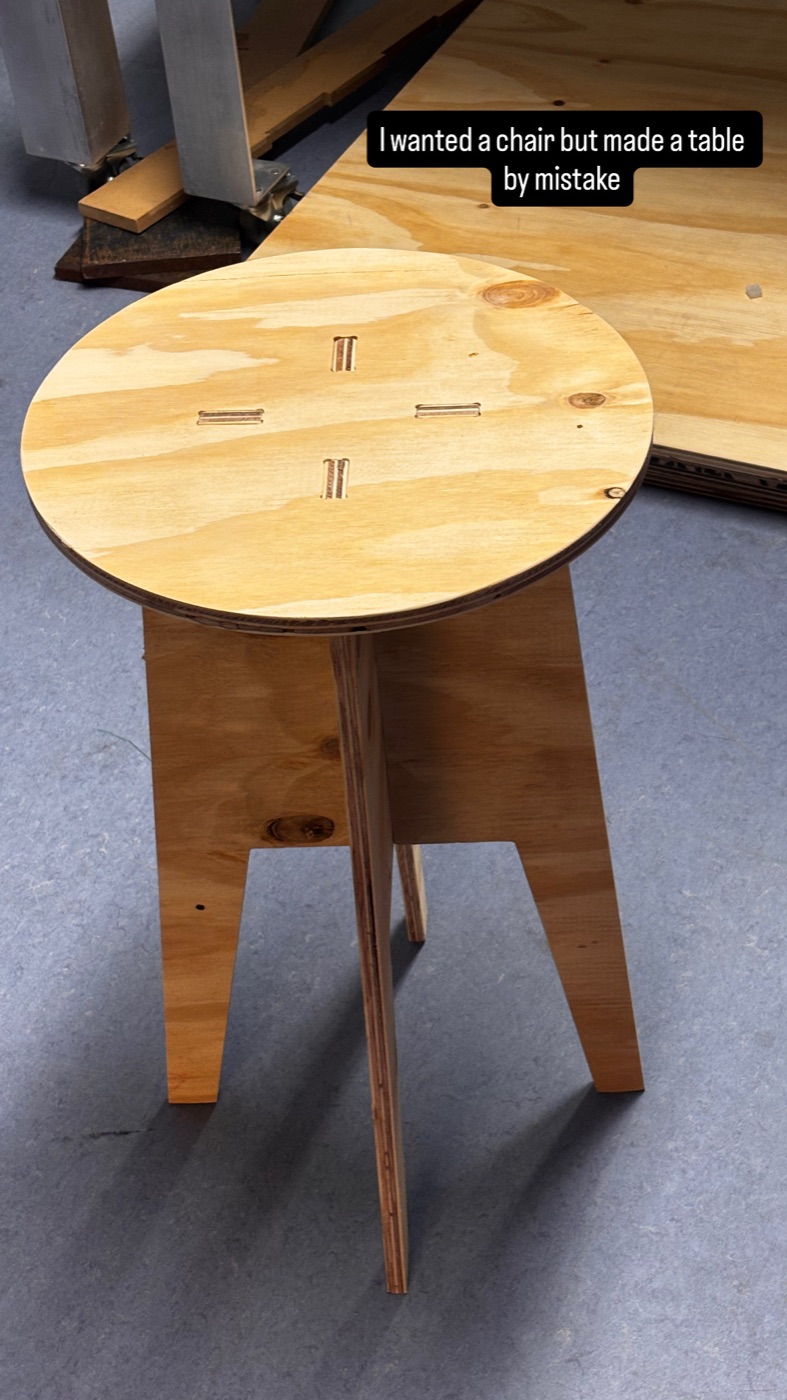
The table is three plywood pieces that press-fit together with finger joints. CNC was the only way to get joint widths consistent enough for the press-fit to hold, and the round top would have been slow to cut by hand.
The FreeCAD file is parametric so I can re-use it later for shelves and other small pieces around the room. Changing the thickness, height or diameter parameter rebuilds the whole table for whatever plywood is at the Fablab that week.
2. Parametric Design in FreeCAD
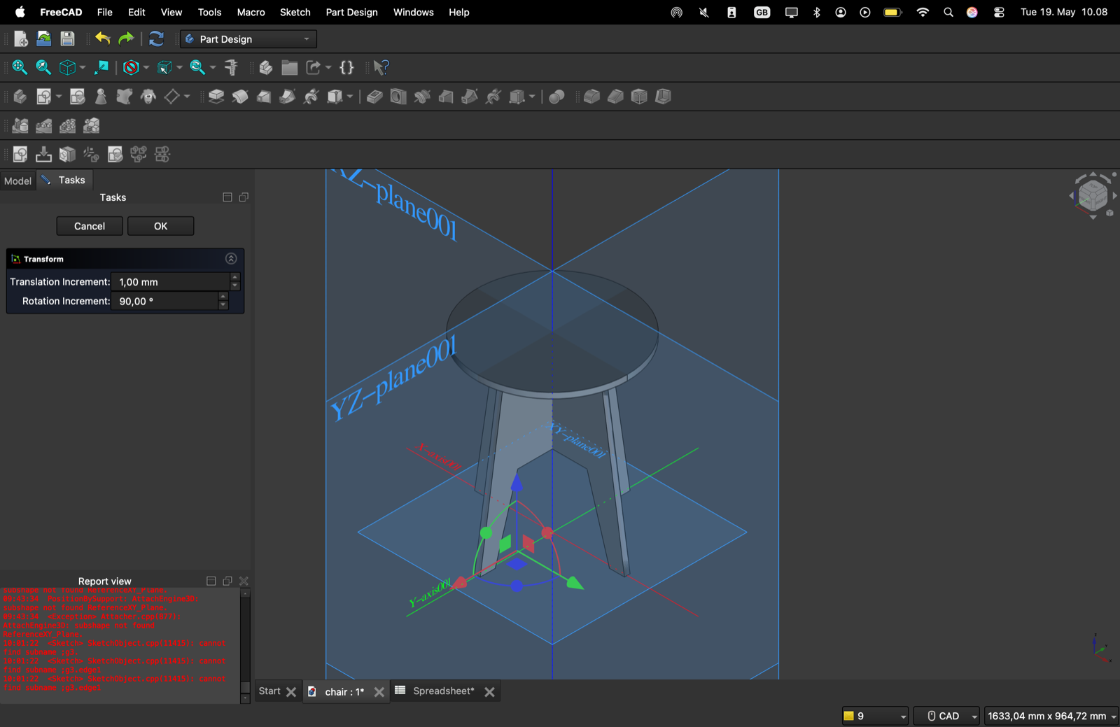
A three-leg table with a round top, all finger joints. The model is driven from a
Spreadsheet with four aliases (Height, Width,
Length and MaterialThickness) set to 14.7 mm. Every
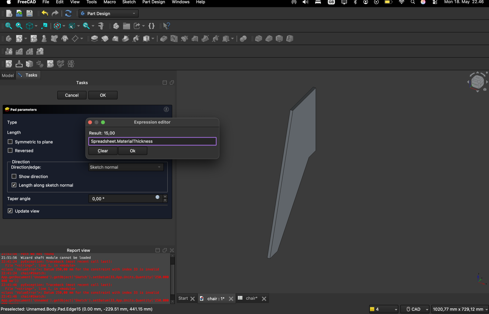
Pad length and every joint width references the spreadsheet through expressions like
=Spreadsheet.MaterialThickness, so editing one cell rebuilds the whole table.
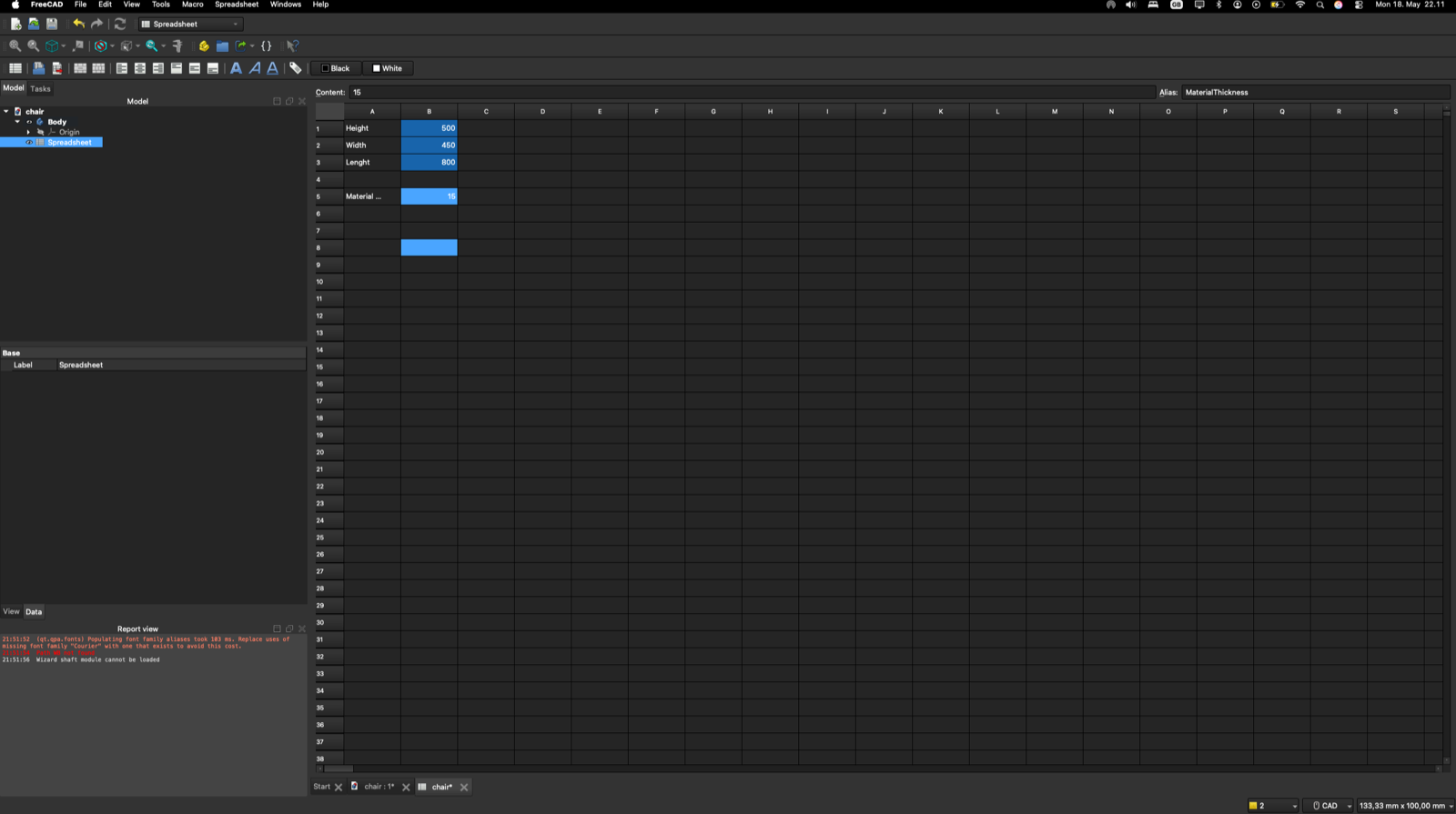
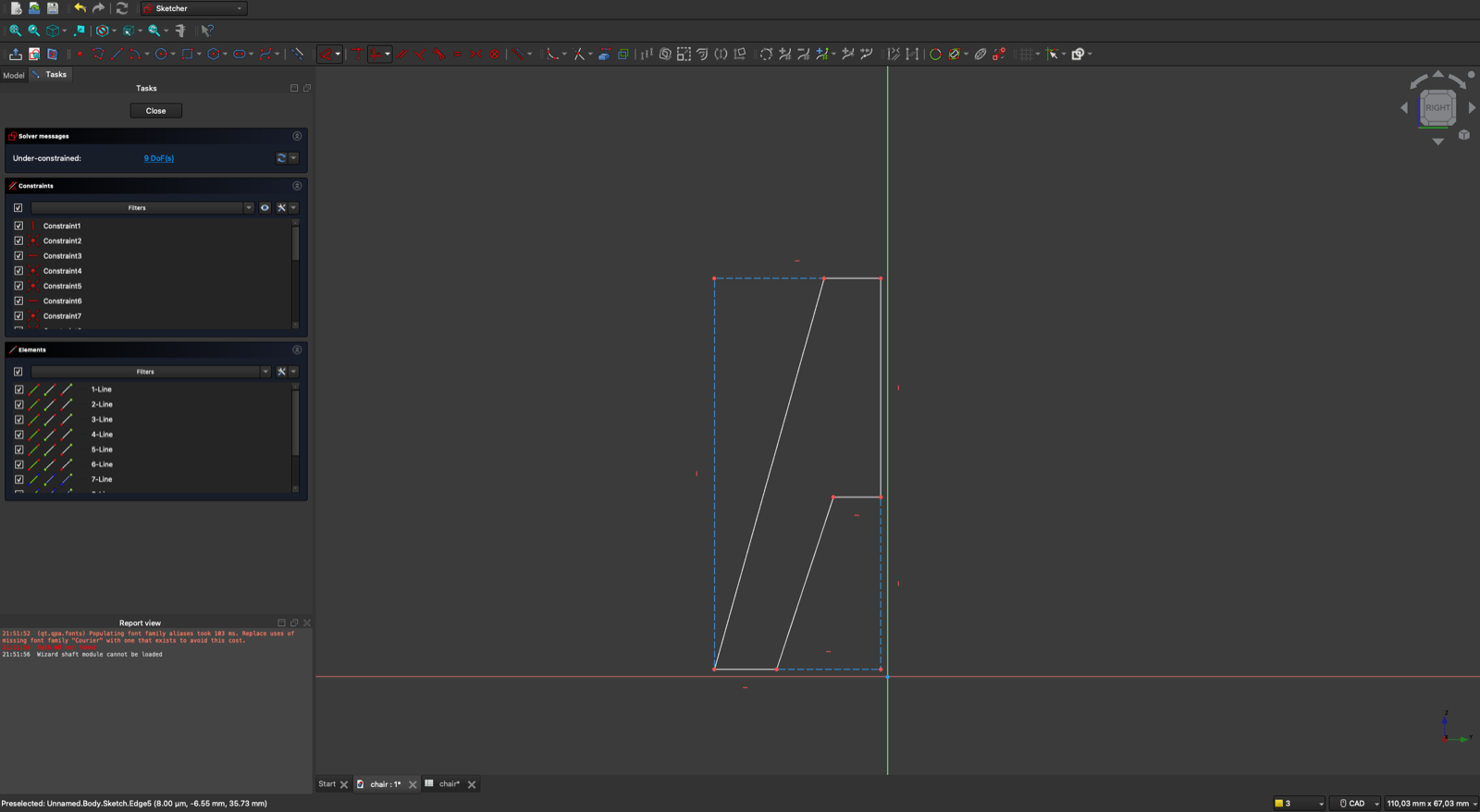
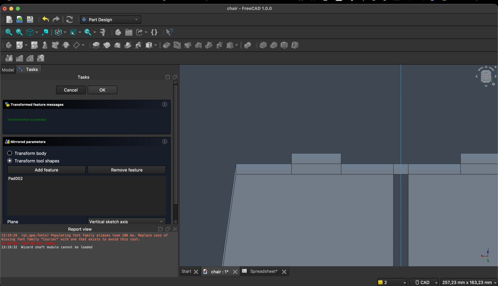
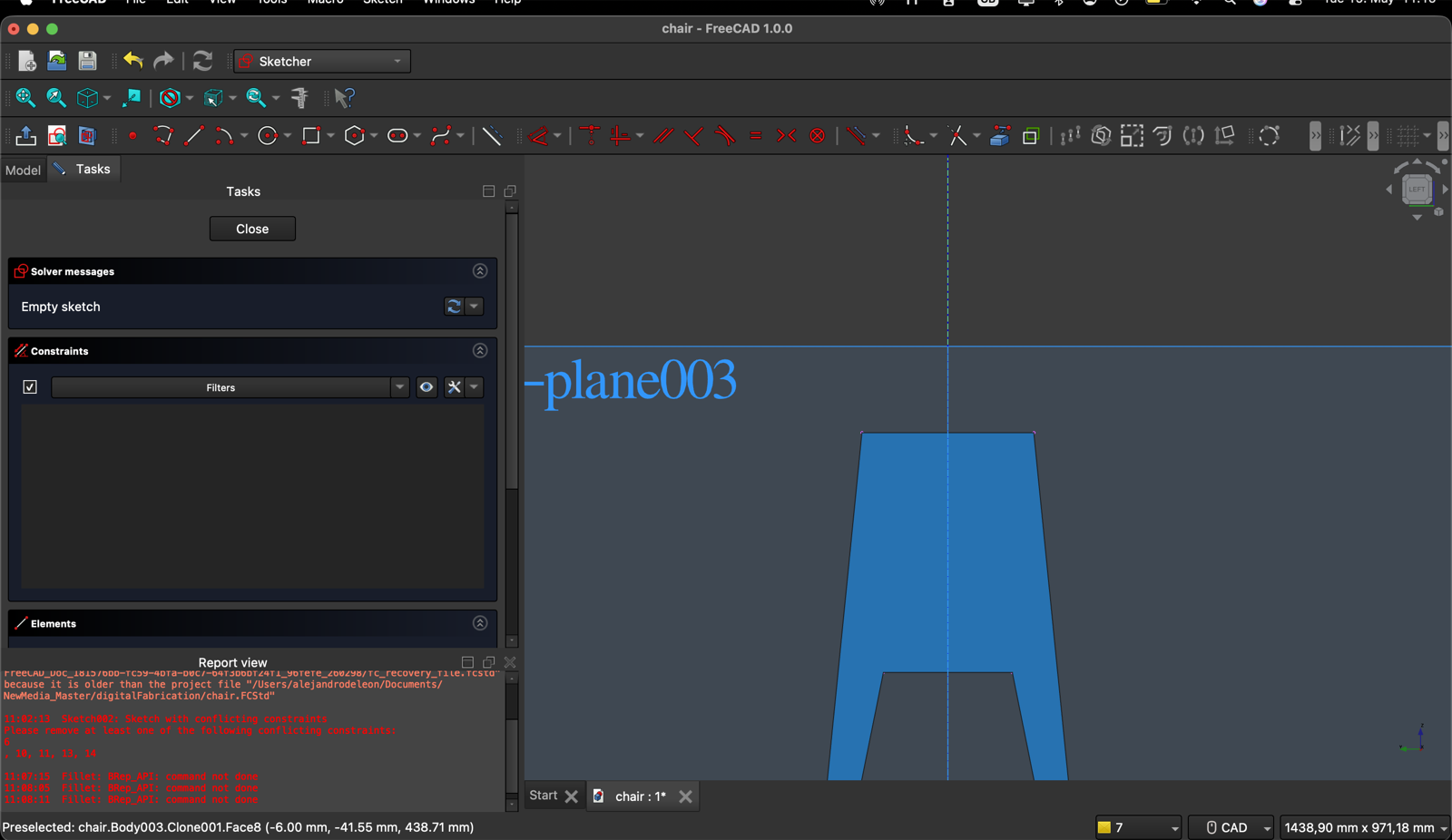
Each leg is half a trapezoid with finger-joint pockets sized to MaterialThickness,
padded, then mirrored across the vertical axis to form a full A-shape. The top is a circle on a
datum plane offset by Height, pocketed with matching slots for the leg tabs.
Spreadsheet.MaterialThickness.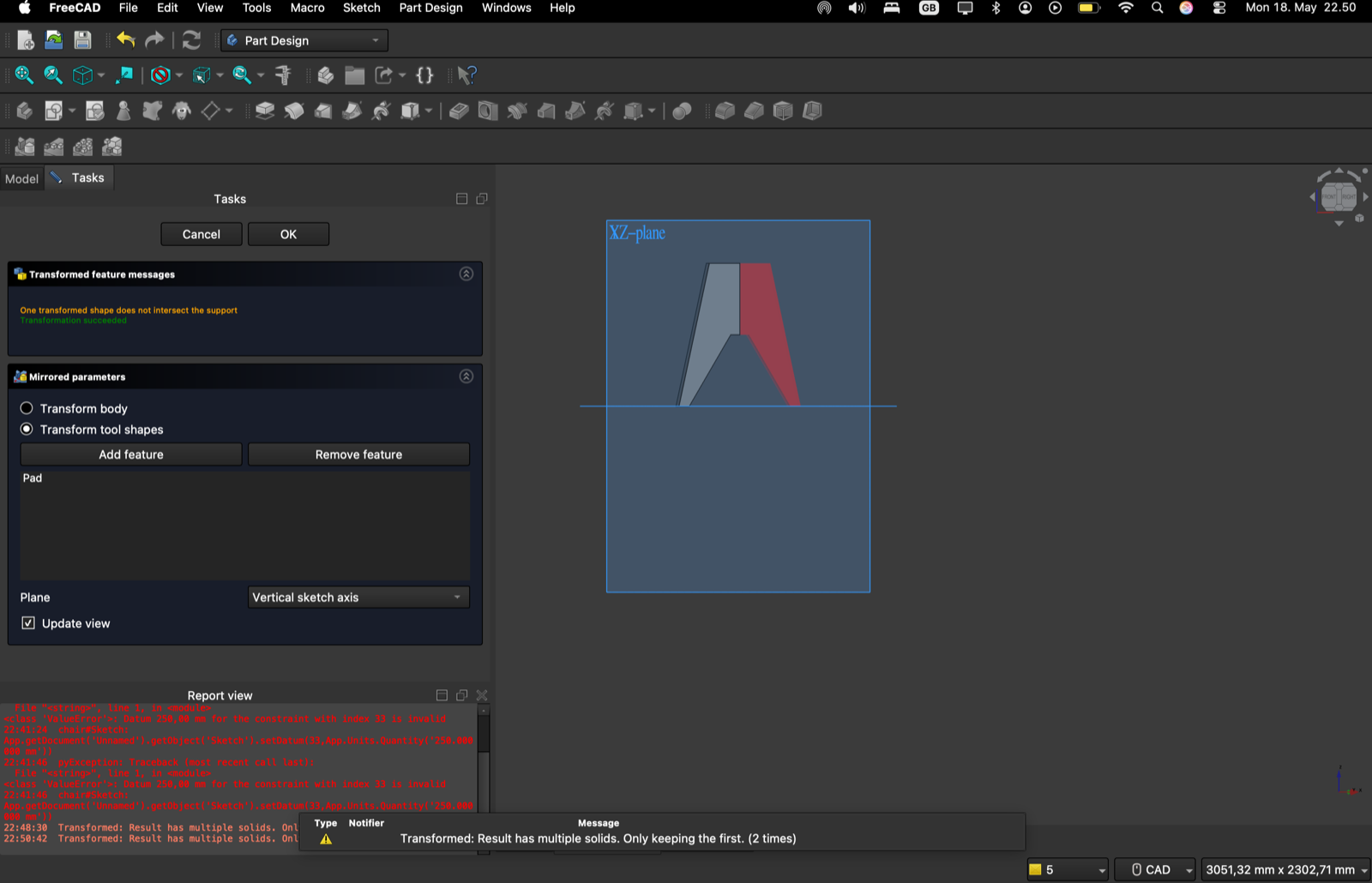
Note on the tool: FreeCAD 1.0 on macOS crashes a lot, especially when editing sketches inside a body that already has a mirrored feature. I saved after every operation.
Download
table.FCStd: the parametric FreeCAD project file.
3. CNC Milling
With MaterialThickness set to 14.7 mm in the spreadsheet, the
model recomputed and I exported the three flat parts (2 legs, 1 top) as DXF for CAM.
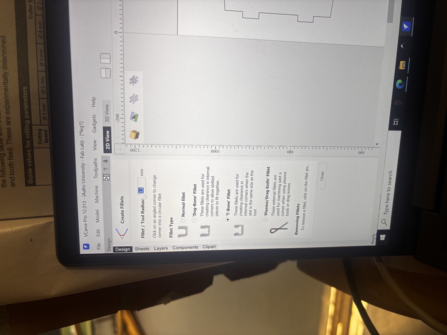
CAM was done at the Aalto Fablab in VCarve Pro 12, cut on the Recontech 1312 3-axis router with a 6 mm flat end mill. The Fablab rule is that the lab manager has to be present when the machine runs, and the wiki is the reference for setup steps. I read through it before booking the slot and kept an eye on the machine the whole time it was cutting.
First the inside corners: I added T-Bone fillets at 3.1 mm tool radius so the male tabs would seat.
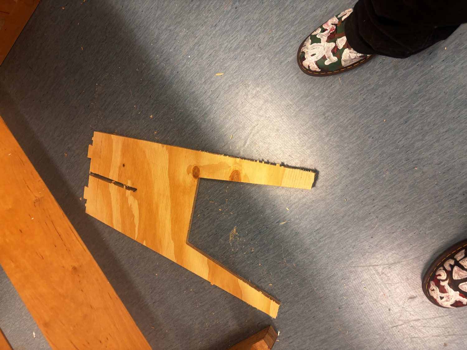
Outside contour: 2D Profile, cut depth 15.2 mm (0.5 mm into the spoilboard), 4 passes, Outside/Right, Climb, with 8 × 4 mm holding tabs on every part. Cut order: pockets, inside contours, outside contour last.

4. Post-Processing and Assembly
I cut the holding tabs off and sanded the edges. Both the cross-lap joint in the middle and the top finger joints came out too tight to push together by hand. I took the male tabs to the Makita belt sander, knocked a little off each face, and tried again. Even after sanding I still needed a rubber mallet to seat the joints.
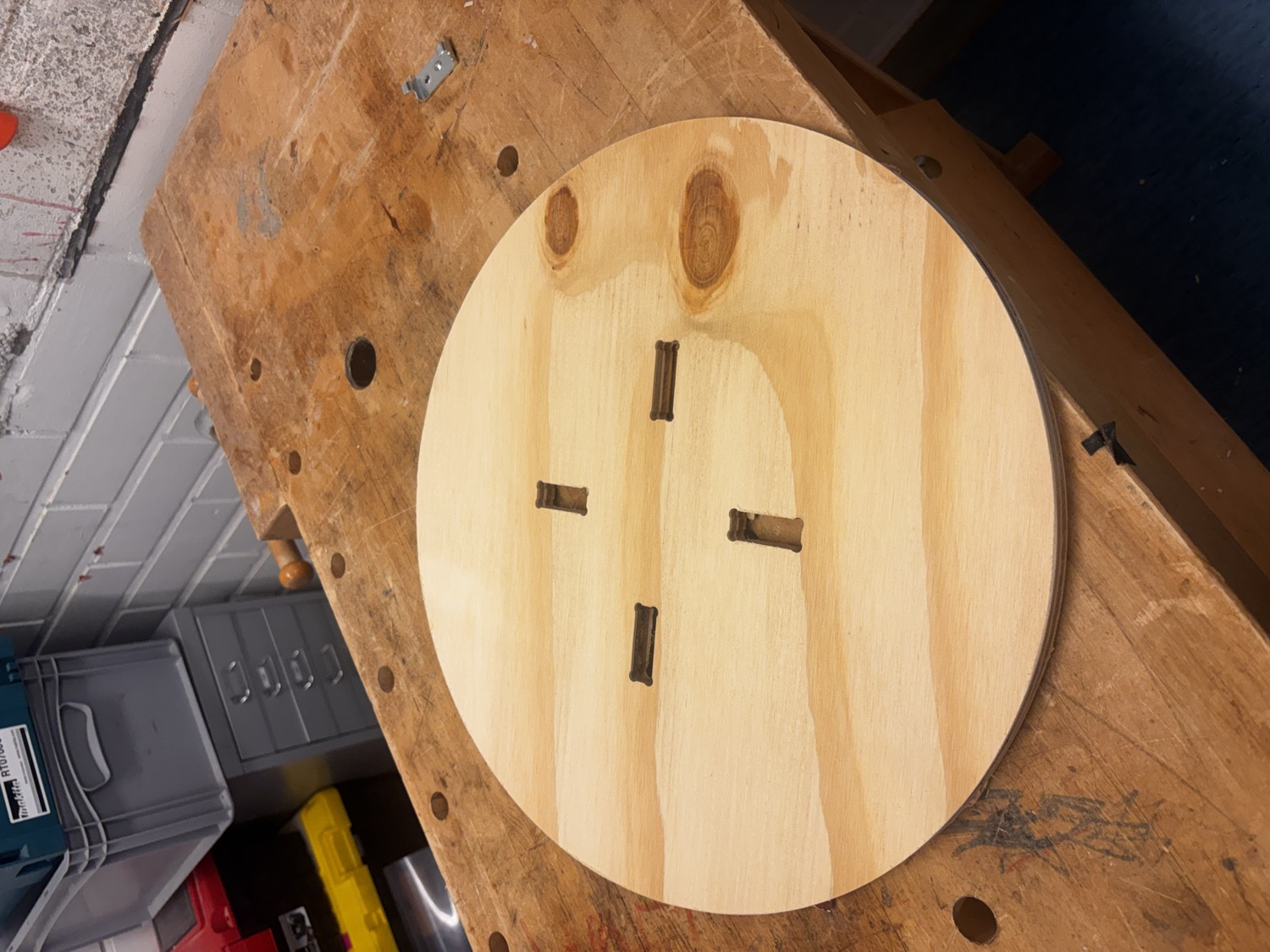
Leg A into leg B first (cross-lap in the middle), then the top dropped on from above and was tapped down with the mallet until flush. No glue, no screws.
5. Reflection
Two things for next time.
Subtract 0.1–0.2 mm per side from the joint width in the spreadsheet. Designing the slots at
exactly MaterialThickness produced joints so tight I had to sand every male tab on
the belt sander before they would start, which defeats half the point of cutting them on the CNC.
Add the dogbones in FreeCAD instead of in CAM, and design around a known end-mill diameter from the start. I patched both in CAM at the last minute, which works but leaves the toolpath less clean than it could be, and means the FreeCAD file doesn't match the part that came off the machine.