0. PCB Manufacturing & My Practice
Well, to start this chapter of the course, I did some research on PCB manufacturing methods and found that there are several approaches to making PCBs, Subtractive methods like milling and chemical etching are great for rapid prototyping and one-off projects, which is ideal for my experimental instrument designs. Additive methods like inkjet printing and 3D printing are still emerging but offer exciting possibilities for custom shapes and flexible circuits. For more polished or production-ready designs, professional fabrication services like JLCPCB or OSHPark provide high-quality PCBs at reasonable prices, especially for small batches. In terms of materials, FR4 is the standard for rigid boards, while flexible substrates can enable wearable or foldable instruments. Overall, I see myself using the milling process for quick iterations in the Fablab using the Roland Monofab SRM-20.
1. PCB Milling & Gerber Files
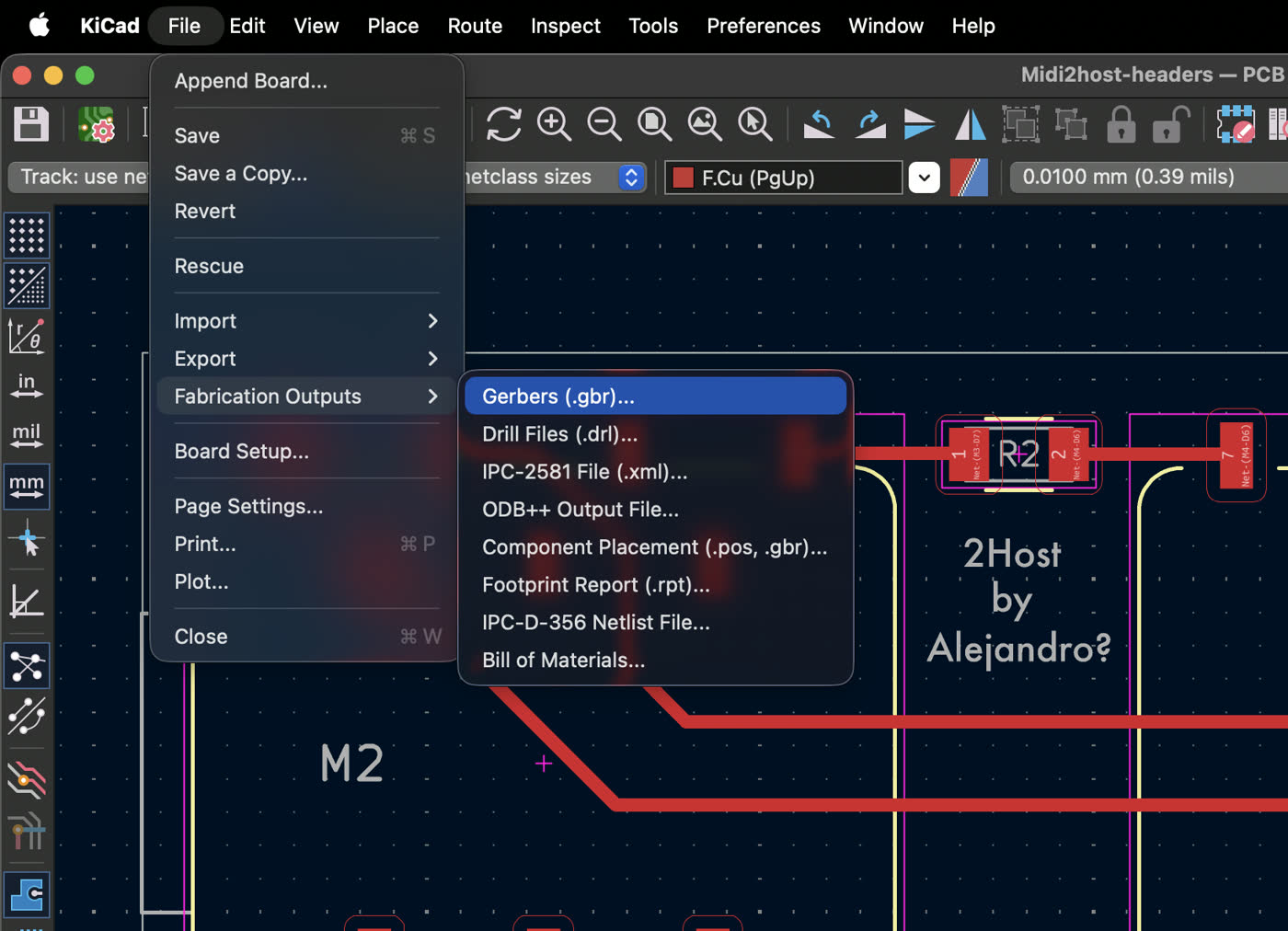
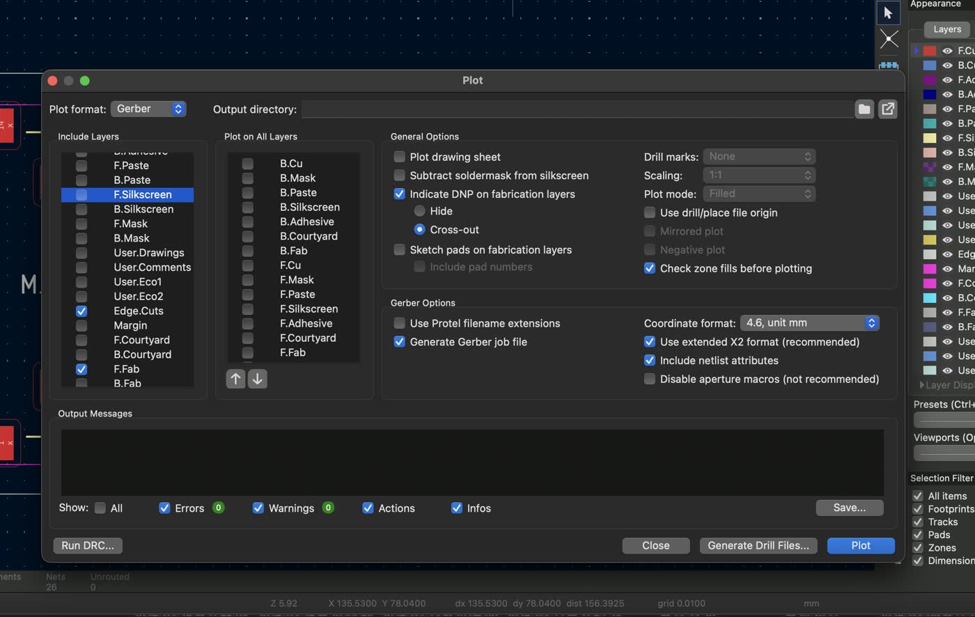
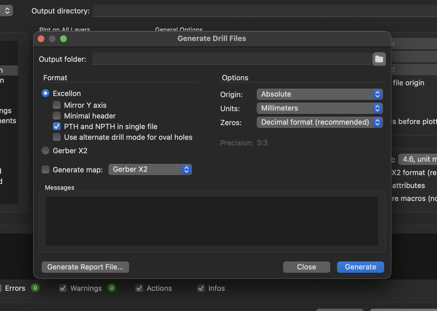
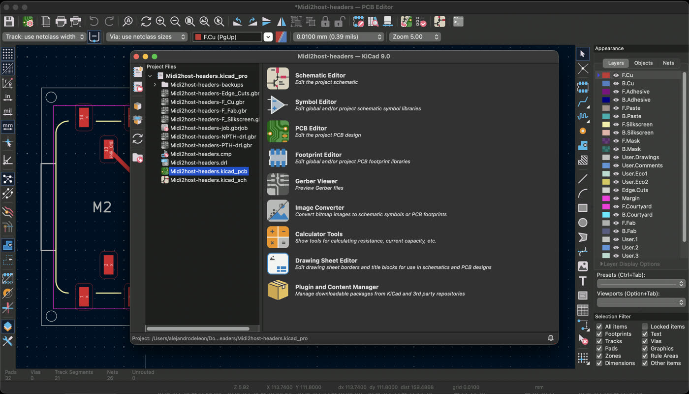
PCB milling is a subtractive manufacturing process where a CNC machine removes (aha! subtraction = removal, get it?) material from a copper board to create the desired circuit patterns, as opposed to chemical etching which uses chemicals to dissolve unwanted copper. Meanwhile, Gerber files are the standard format for PCB manufacturing, containing all the necessary information for each layer of the board (copper, solder mask, silkscreen, etc.). These files are then converted into tool paths using software like CopperCAM where you can set parameters such as bit diameter, cut depth, feed rate, and spindle speed. Common issues during milling include insufficient isolation width between traces, missing drill hits for vias or holes, and board warping due to uneven material removal. For this project, I exported my Gerber files from KiCad by selecting the appropriate layers (in my case they were only P.Cu and F.Fab and Edge.Cuts) and configuring the output settings to ensure compatibility with the milling software.
2. Milling the Board
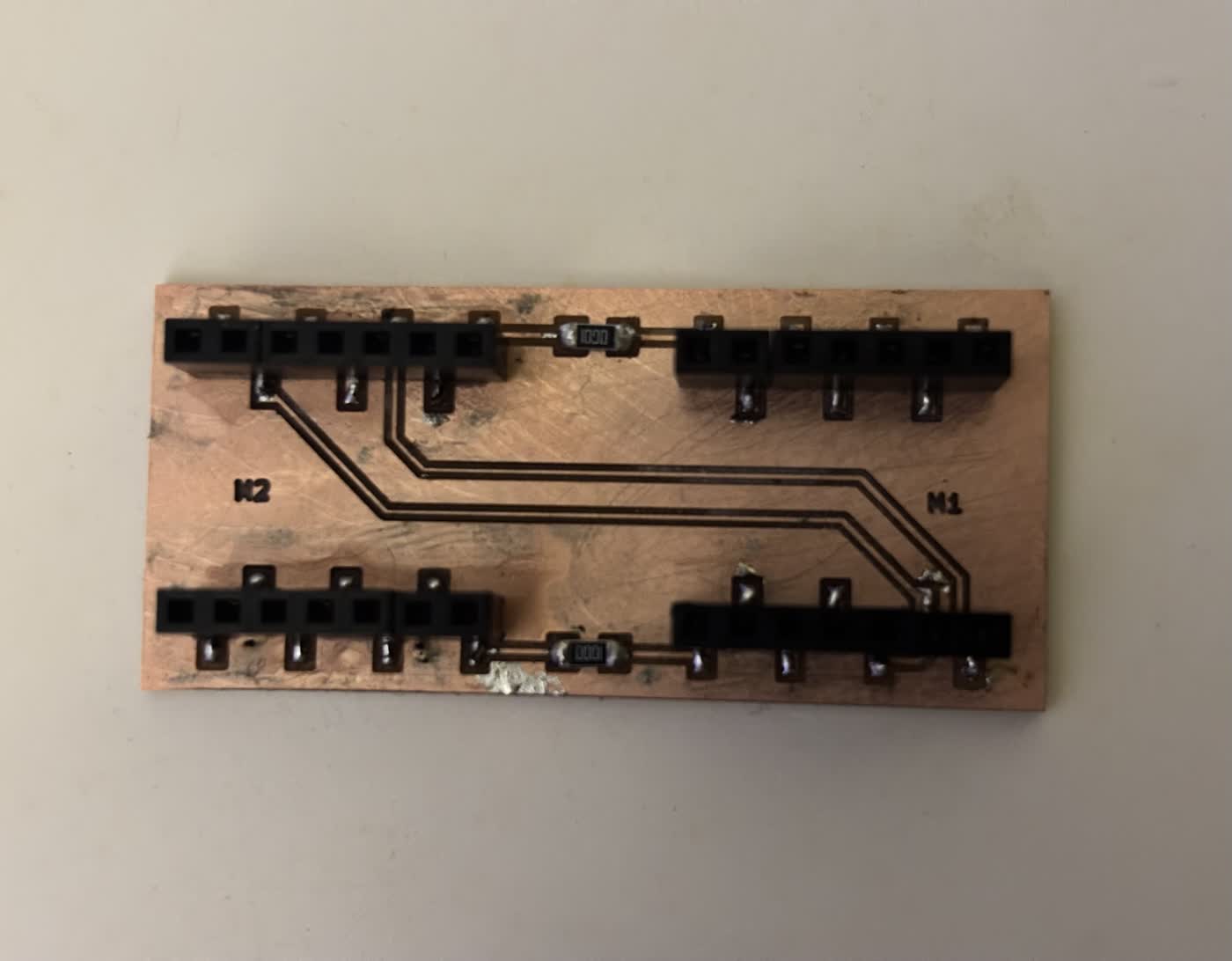
Once, I exported everything I set it on my USB and went to the machine, which is a Roland Monofab SRM-20, a popular desktop CNC mill for PCB prototyping. I measured the thickness of the copper-clad sheet using a caliper and securely fixed it to the machine bed using double-sided tape to prevent any movement of the board during the milling. As it was my first time, the Fablab assistant, Zofia, gave me a hand with the software and how to set the bridle and also to level it on all angles (X, Y, Z). I set the X/Y origin at the bottom-left corner of the board by jogging the machine to that position and setting it as the home point in the software. For the Z origin, we adjusted the height to be as close as the bed as possible and then set the bridle loose so the 0 level is right on top of the copper surface, then retightened it. We used CopperCAM to load the Gerber files and generate the tool paths, and then sent the job to the machine. The milling process went smoothly overall, although I set the text wrong as I imported the wrong layer so the first board didn't have any text. I also had to re-run one of the layers due to a minor issue because of the Z level with the initial cut, but in the end, I was able to successfully mill both of my PCB designs without any major problems.
3. Populating & Soldering the Board
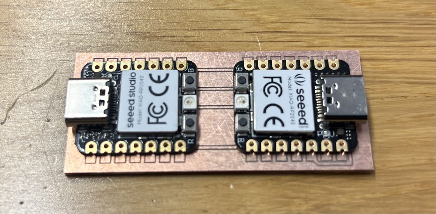
Populating the board was honestly the most hands-on part of the whole process. The MIDI Bridge design doesn't have many components — mostly pin headers for the two XIAO RP2040 modules to sit in, and a couple of SMD resistors. I started with the SMD parts first since they're easier to solder before the headers are in the way, then moved on to the pin headers. I made sure they were flush and straight before letting the solder cool, since the XIAO modules need to seat properly into them.
4. Writing & Uploading Test Code
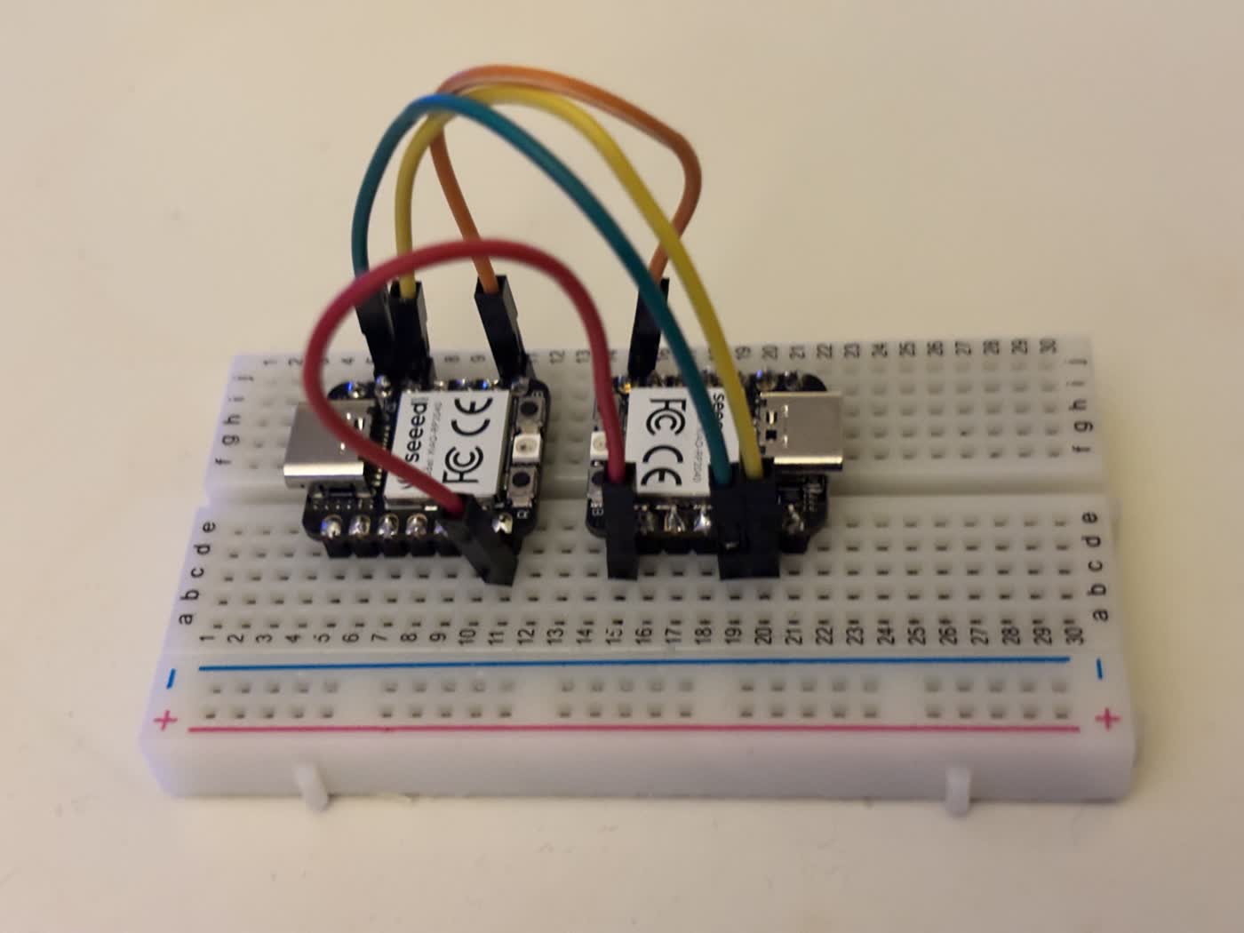
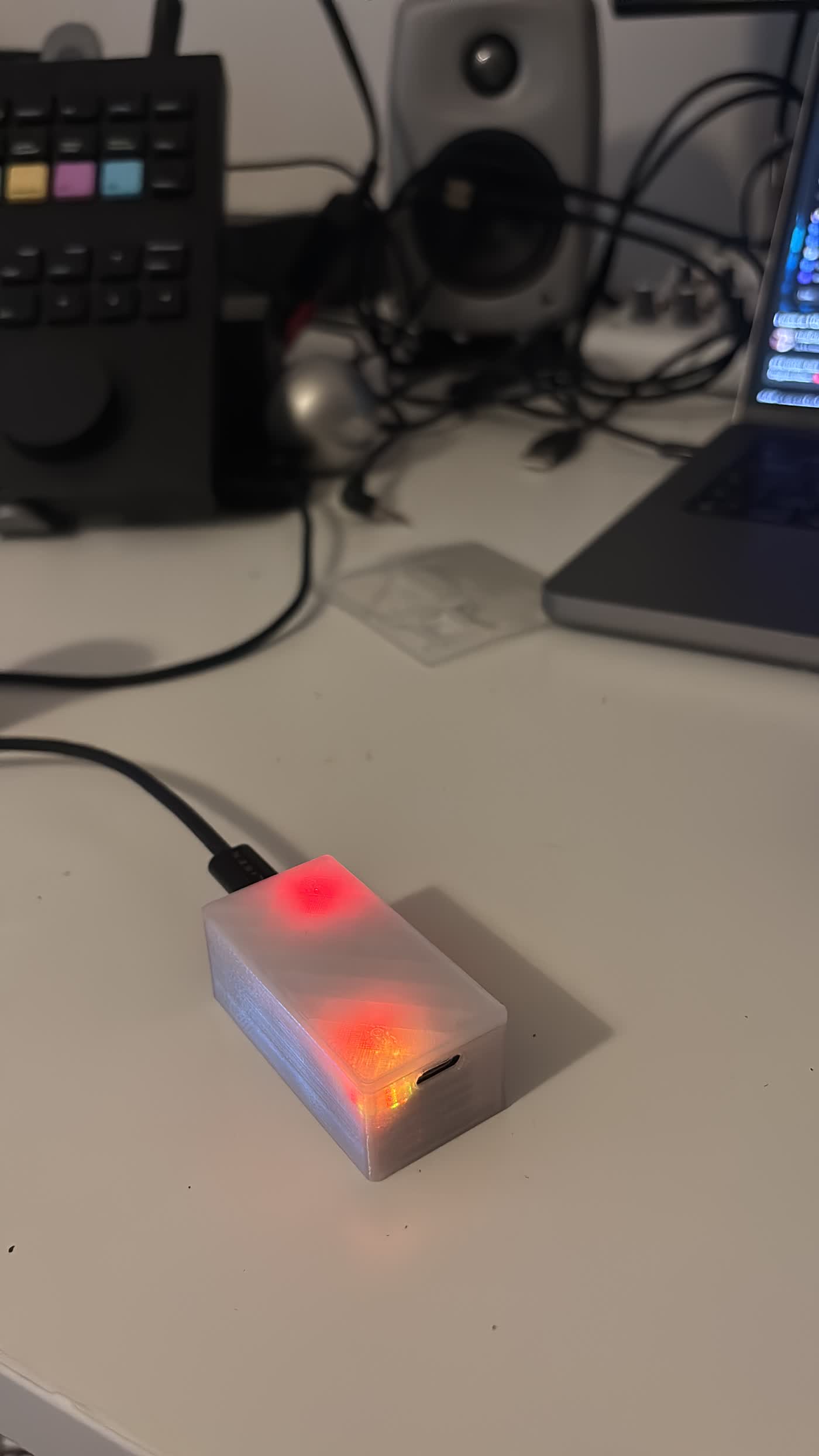
Before seating the XIAOs on the milled board, I wired them up on a breadboard first to verify the UART communication between them. Once I was happy that was working, I seated them on the board and started uploading the code. The real goal was to use the board to bridge MIDI between my Norns and my computer running Ableton — so I could run SNU, a step sequencer a friend and I made for the Norns, and have it drive my Ableton plugins. And it worked — once I plugged the board in and opened Ableton, the MIDI messages from SNU came through and started triggering everything.
// MIDIHost2Host -- Seeed XIAO RP2040
// Forwards MIDI between USB and hardware Serial1 (D6=TX, D7=RX)

#include <Arduino.h>
#include <Adafruit_TinyUSB.h>
#include <MIDI.h>

// --- Board selection ---
//#define RED_BOARD
#define BLUE_BOARD

// --- XIAO RP2040 onboard RGB LED pins (active LOW) ---
#define LED_R_PIN  17
#define LED_G_PIN  16
#define LED_B_PIN  25

// --- Board identity ---
#ifdef RED_BOARD
  char mfgstr[32] = "Alejandro?";
  char prodstr[32] = "2Host Red";
#else
  char mfgstr[32] = "Alejandro?";
  char prodstr[32] = "2Host Blue";
#endif

// --- USB MIDI + Hardware Serial1 ---
Adafruit_USBD_MIDI usb_midi;
MIDI_CREATE_INSTANCE(Adafruit_USBD_MIDI, usb_midi, midiA);
MIDI_CREATE_INSTANCE(HardwareSerial,     Serial1,  midiB);

// --- LED blink state ---
bool     led_on      = false;
uint32_t led_time    = 0;
uint32_t led_on_time = 50;

// --- RGB LED helpers (active LOW) ---
void set_rgb(bool r, bool g, bool b) {
  digitalWrite(LED_R_PIN, r ? LOW : HIGH);
  digitalWrite(LED_G_PIN, g ? LOW : HIGH);
  digitalWrite(LED_B_PIN, b ? LOW : HIGH);
}

void flash_color(bool r, bool g, bool b) {
  set_rgb(r, g, b);
  led_on   = true;
  led_time = millis();
}

void led_check() {
  if (led_on && (millis() - led_time) > led_on_time) {
    led_on = false;
    // Return to idle color
    #ifdef RED_BOARD
      set_rgb(true, false, false);  // dim red idle
    #else
      set_rgb(false, false, true);  // dim blue idle
    #endif
  }
}

void setup() {
  Serial.begin(115200);

  pinMode(LED_R_PIN, OUTPUT);
  pinMode(LED_G_PIN, OUTPUT);
  pinMode(LED_B_PIN, OUTPUT);

  // Yellow = booting
  set_rgb(true, true, false);

  USBDevice.setManufacturerDescriptor(mfgstr);
  USBDevice.setProductDescriptor(prodstr);

  // Init hardware Serial1 FIRST at MIDI baud rate
  Serial1.begin(31250);

  // Then init MIDI on top
  midiA.begin(MIDI_CHANNEL_OMNI);
  midiB.begin(MIDI_CHANNEL_OMNI);
  midiA.turnThruOff();
  midiB.turnThruOff();

  // Wait for USB mount
  while (!USBDevice.mounted()) delay(1);

  // Show idle color
  #ifdef RED_BOARD
    set_rgb(true, false, false);
    Serial.println("RED ready");
  #else
    set_rgb(false, false, true);
    Serial.println("BLUE ready");
  #endif
}

void loop() {

  // --- USB MIDI -> Serial MIDI ---
  if (midiA.read()) {
    midi::MidiType type = midiA.getType();
    byte data1   = midiA.getData1();
    byte data2   = midiA.getData2();
    byte channel = midiA.getChannel();
    midiB.send(type, data1, data2, channel);
    flash_color(true, true, false);  // yellow flash = USB->Serial
    Serial.println("USB->Serial");
  }

  // --- Serial MIDI -> USB MIDI ---
  if (midiB.read()) {
    midi::MidiType type = midiB.getType();
    byte data1   = midiB.getData1();
    byte data2   = midiB.getData2();
    byte channel = midiB.getChannel();
    midiA.send(type, data1, data2, channel);
    flash_color(false, true, false);  // green flash = Serial->USB
    Serial.println("Serial->USB");
  }

  led_check();
}
The code runs on both XIAO boards — you just change one line (#define RED_BOARD or #define BLUE_BOARD)
before flashing each one, so they each know their role.
Each board sits in the middle and does one thing: whatever MIDI comes in from one side, it immediately passes it out the other.
One side is USB MIDI — so your computer sees the board as a MIDI device — and the other side is hardware Serial
(the TX/RX pins), which is how the two boards talk to each other, and how classic MIDI gear communicates.
So the signal path is: Norns → Serial → board → USB → computer (Ableton), and back the same way.
The RGB LED is just for feedback — it glows red or blue at idle depending on which board it is,
flashes yellow when a message goes USB→Serial, and green when it goes Serial→USB,
so you can actually see the MIDI flowing.
5. Project Files
Download the KiCad project files for the MIDI Bridge board: MIDI2Host.zip