0. Design Concept
I couldn't complete the assignment as I was not able to compose 3 parts that could be cut and snap together. I had a hard time coming up with a design that met these requirements, and I struggled to figure out how to create the necessary geometry in FreeCAD.
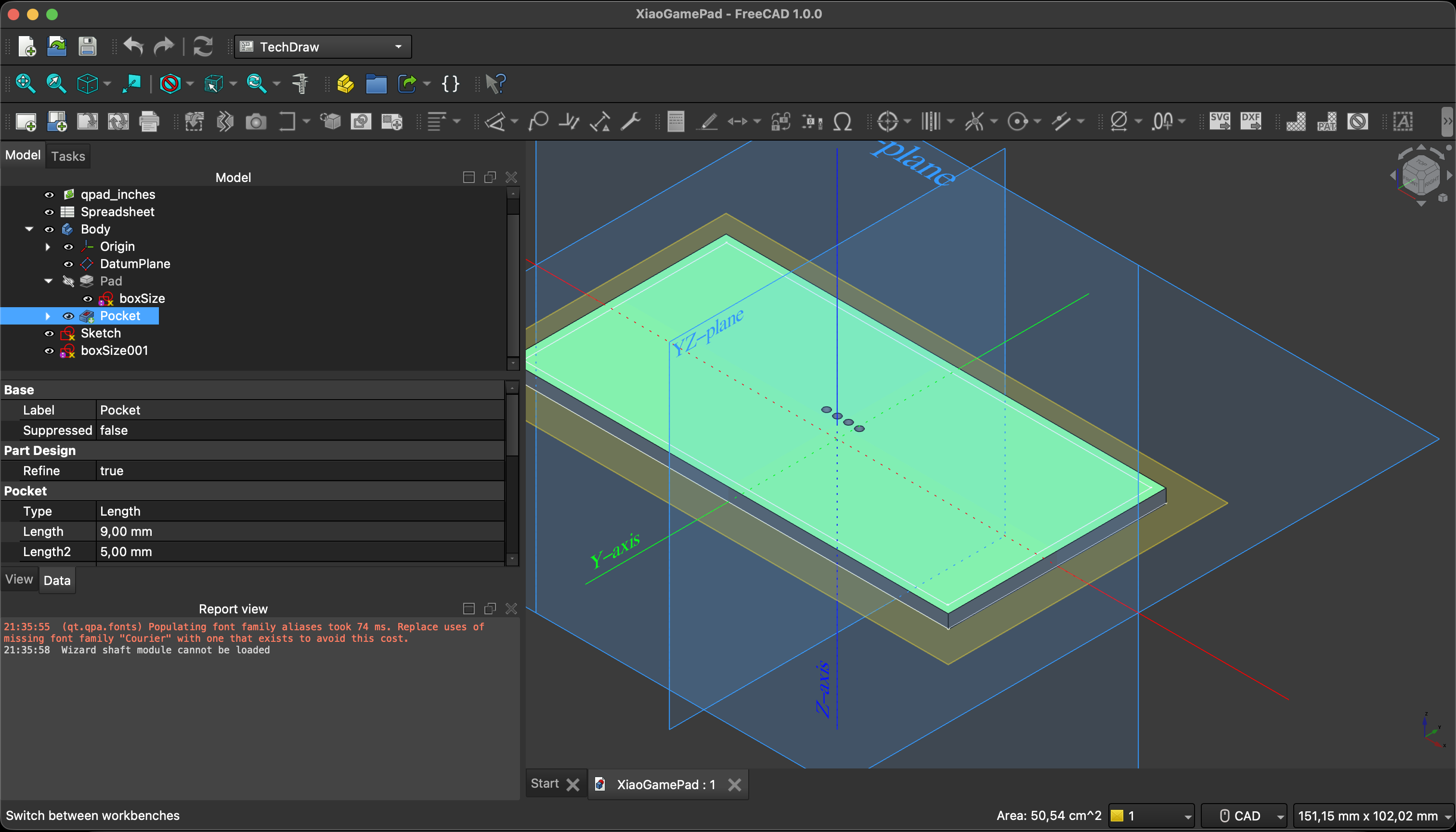
1. Parametric Design in FreeCAD
I created a parametric design in FreeCAD using the Spreadsheet workbench to define parameters such as material thickness and slot widths. I linked these parameters to the dimensions in my sketch and part design, allowing me to easily adjust the design by changing the values in the spreadsheet.
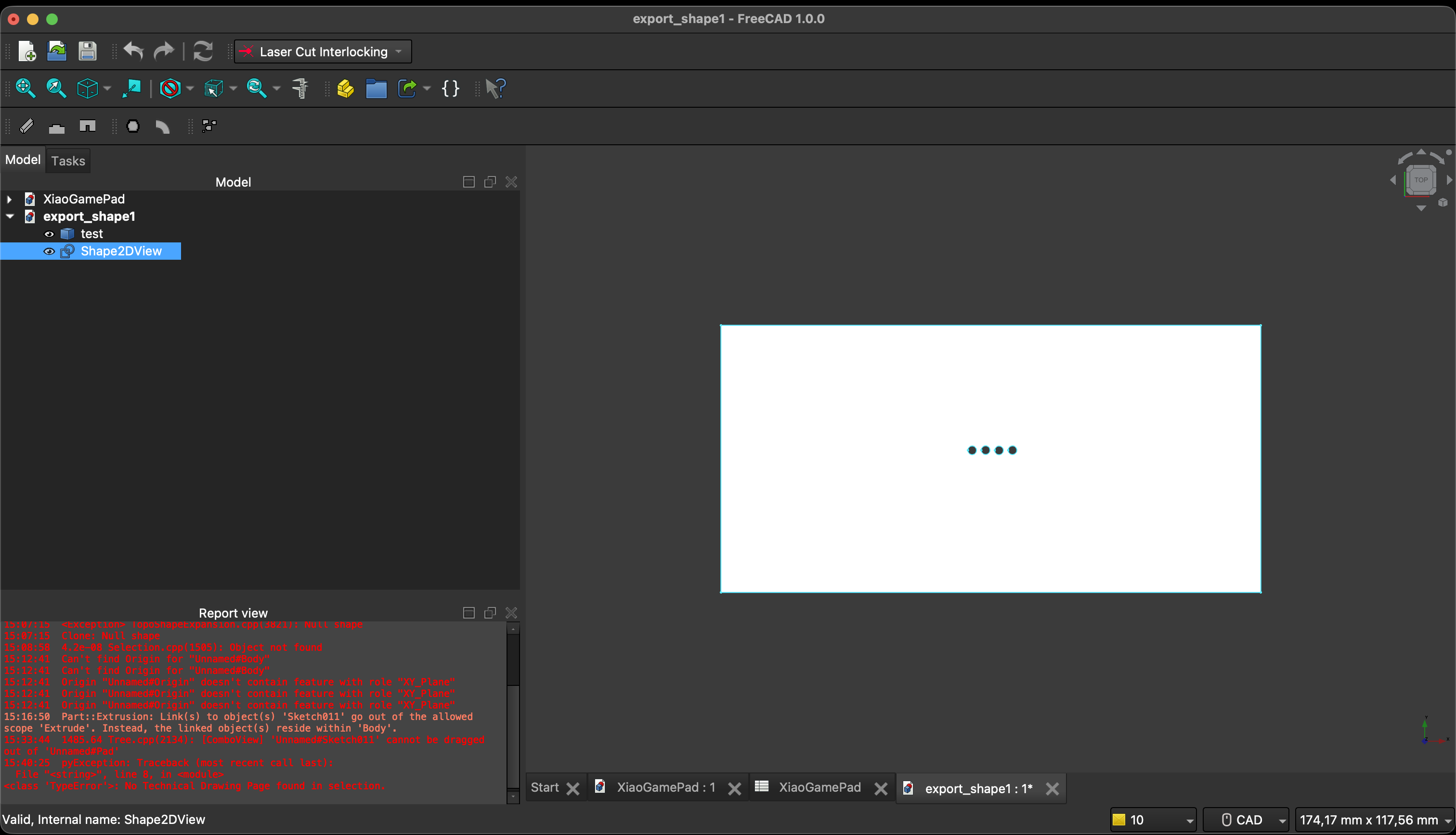
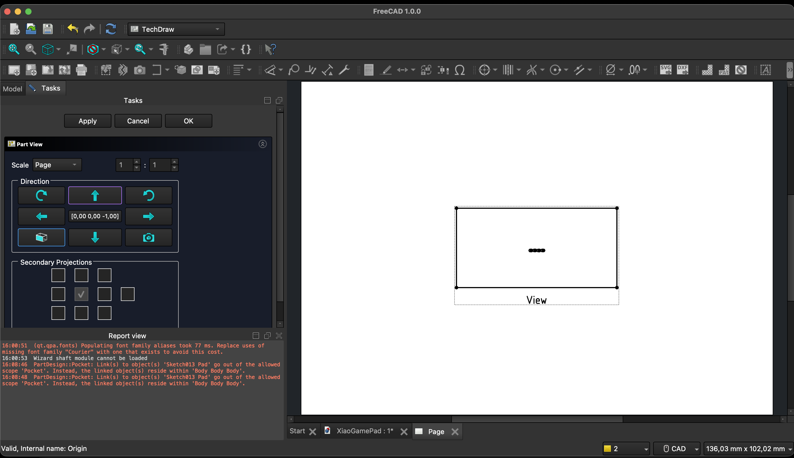
2. Laying Out Parts — TechDraw & Inkscape
I used the TechDraw workbench to create a drawing of the parts and then exported it as an SVG file. I opened the SVG in Inkscape to clean up the layout and prepare it for laser cutting. In Inkscape, I adjusted the stroke widths to ensure that cut lines were set to a specific width for cutting (e.g., 0.01mm). I reused some material there to minimize material waste.
Download the SVG cutting file: xiao-pad-base.svg
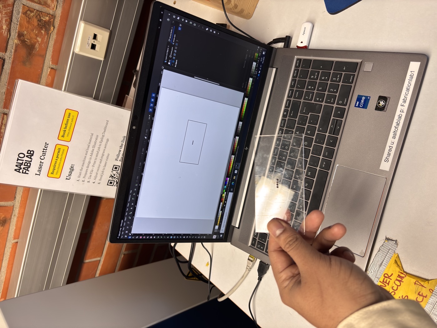
3. Laser Cutting — Epilog Dashboard & Results
I used the Epilog Dashboard software to set up the cutting parameters for the material I was using (e.g., 3mm acrylic cutting). I imported the SVG file into the dashboard, set the appropriate power, speed, and frequency settings for cutting, and then sent the job to the laser cutter. I then check the level of the bed and the focus of the laser before starting the cut. I set the extractor and then pressed start. The machine cut the parts according to the design.
4. Project File
Download the FreeCAD project file: assignment-03-04.zip