0. My Background & Goals with CAD
I am pretty new to CAD software, and in the past I have used blender for 3d modelling yet I am definitely no expert. Regarding other 3d stuff, I have done photogrammetry, 3d web development with three.js and experimented with unity too. My goals with CAD are to be able to design cases and accessories for my electronics projects, and to be able to create custom parts for whatever project I imagine.
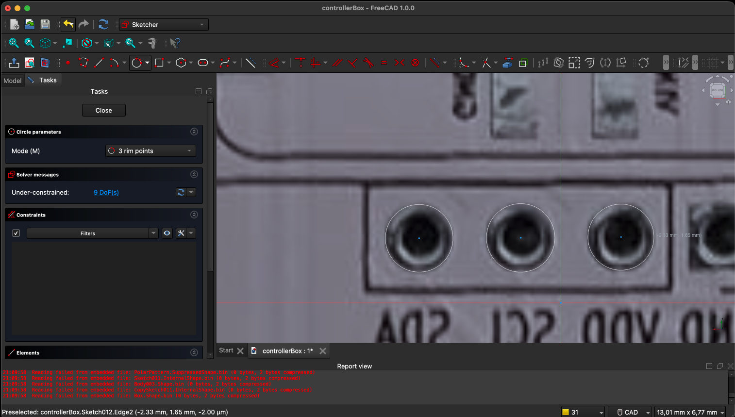
1. Sketcher Workbench — 2D Sketch
It has been a bit complicated to get used to the sketcher workbench, but I have been able to create a simple 2D sketch with some construction geometry. I started by creating a new sketch on the XY plane and used the circle tool to create the holes for the case. I then added some construction lines to help with alignment and symmetry.
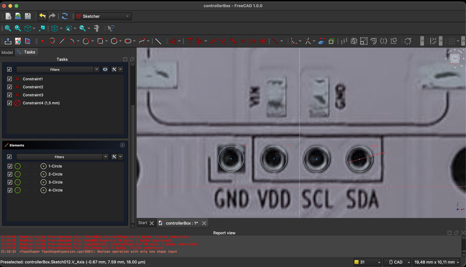
2. Fully Constraining the Sketch
I applied constraints such as horizontal, vertical, and diameter to fully define the sketch. It was a bit tricky to figure out which constraints to apply and in what order, but after some trial and error, I was able to get everything fully constrained. The sketch is now ready for further operations in the Part Design workbench.
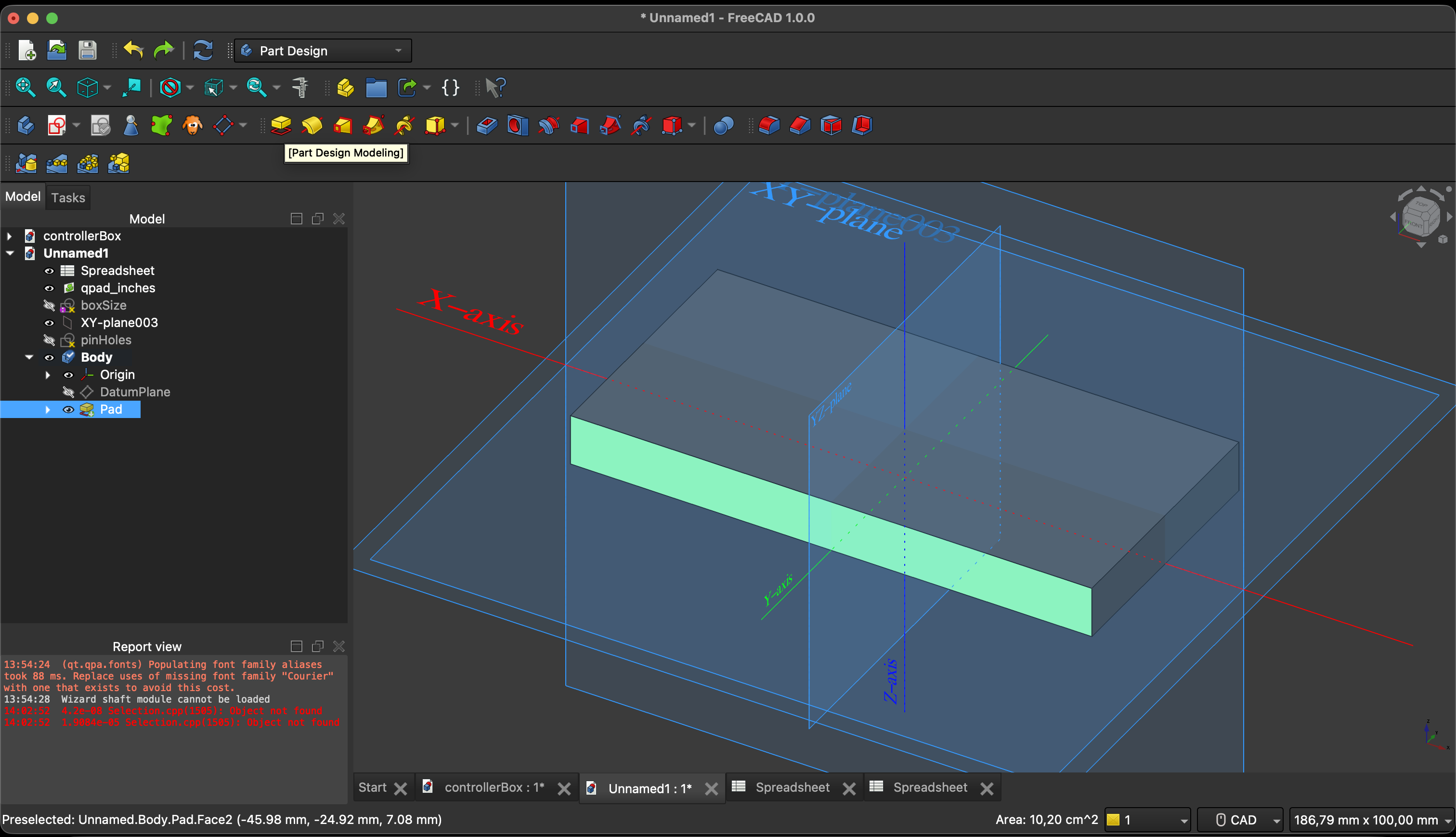
3. 3D Shape Creation — Part Design Workbench
Shape got hands, I am not the most intelligible person when it comes to 3D modelling, but I was able to create a simple base panel for the controller using the Pad operation to extrude the sketch, and then I used the Pocket operation to cut out the holes for the buttons and screen. I missed using the Fillet operation to round the edges of the case for a smoother finish.
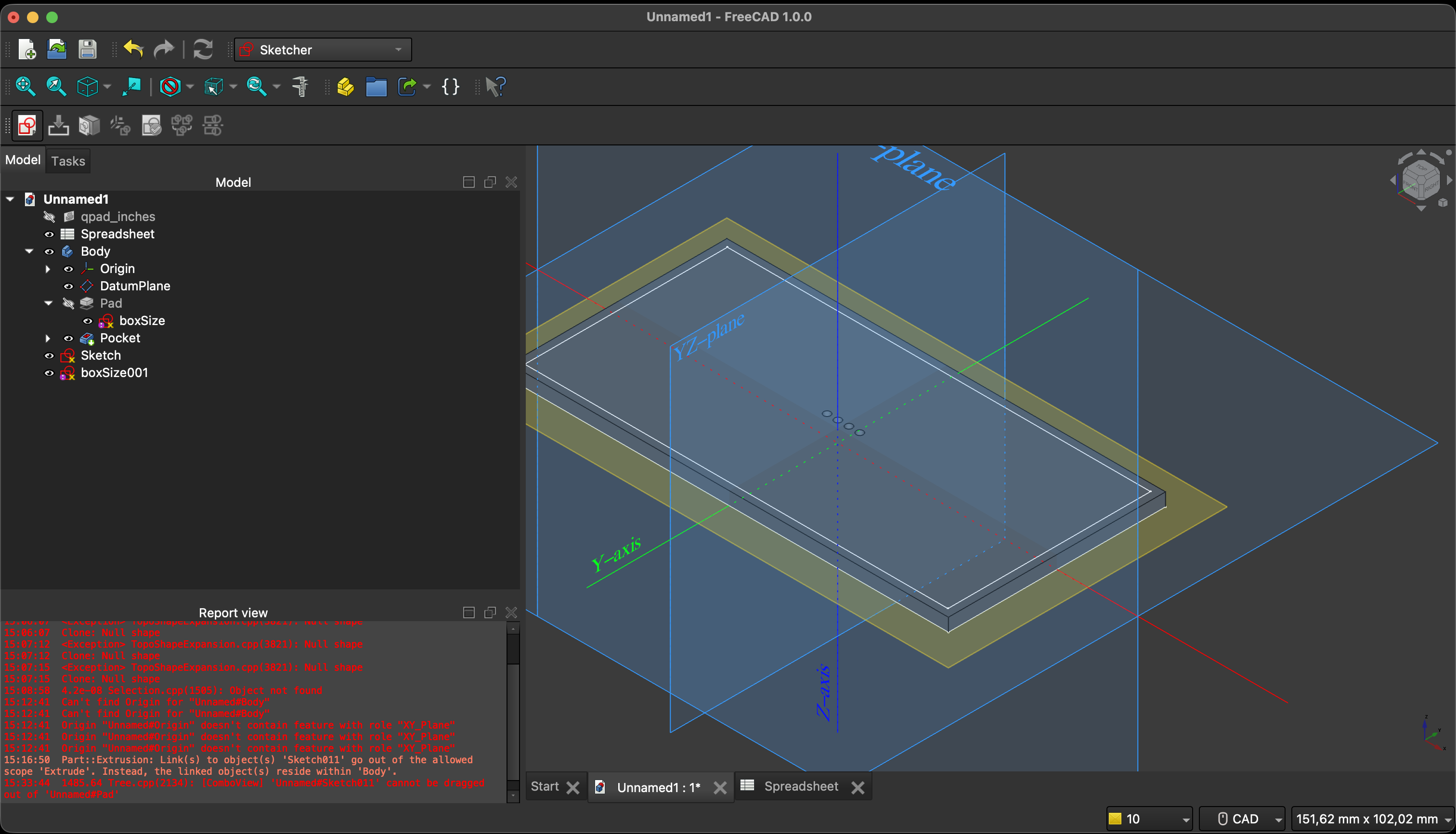
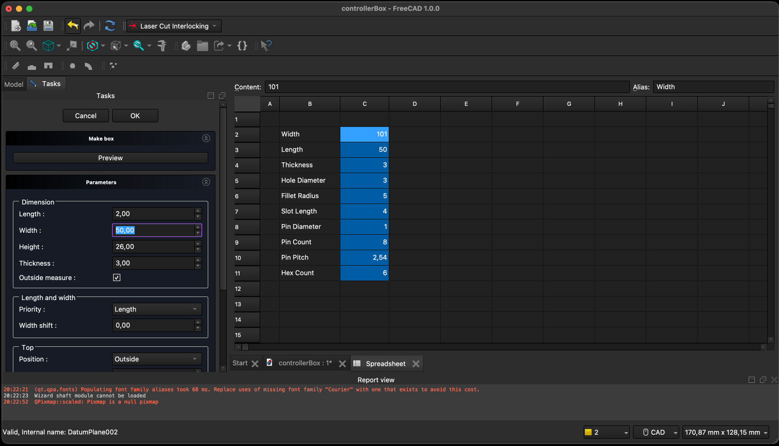
4. Parametric Design — Spreadsheet Workbench
I used the Spreadsheet workbench to create a parametric design by defining key dimensions and parameters in a spreadsheet. I linked these parameters to the 3D model using expressions, allowing me to easily update the design by changing values in the spreadsheet. For example, I defined parameters for the overall width, height, and depth of the case, as well as the diameter of the holes. This approach made it easy to iterate on the design and quickly make adjustments without having to manually edit the geometry in the sketch or part design workbench.
Download the FreeCAD project file: assignment-03-04.zip